Horizontal type multi-target vacuum sputtering or ion plating machine

A technology of vacuum sputtering and coating machine, which is applied in the direction of sputtering coating, ion implantation coating, vacuum evaporation coating, etc., and can solve problems such as the effect of barrel plating on difficult workpieces, poor adaptability of coated parts, and environmental pollution. , to achieve the effect of improving the quality of the coating of the workpiece, making it easy to enter and exit, and improving the quality of the coating

Active Publication Date: 2013-09-11
宁波韵升装备技术有限公司 +2
View PDF5 Cites 11 Cited by
  • Summary
  • Abstract
  • Description
  • Claims
  • Application Information

AI Technical Summary

Problems solved by technology

[0002] Electroplating has been used in industry for a long time, but due to the serious environmental pollution caused by the discharge of three wastes in the electroplating process, a large amount of investment is required to treat it and it is difficult to cure it. It is the vertical multi-target vacuum sputtering or ion coating machine that has been developed rapidly. It is mainly used for rack plating. Its disadvantage is that it is more suitable for the coating of specific workpieces. Realize the effect of workpiece barrel plating

Method used


Image

  • Horizontal type multi-target vacuum sputtering or ion plating machine
  • Horizontal type multi-target vacuum sputtering or ion plating machine
  • Horizontal type multi-target vacuum sputtering or ion plating machine

Examples


Embodiment Construction

[0025] The present invention will be further described below in conjunction with the accompanying drawings and embodiments.

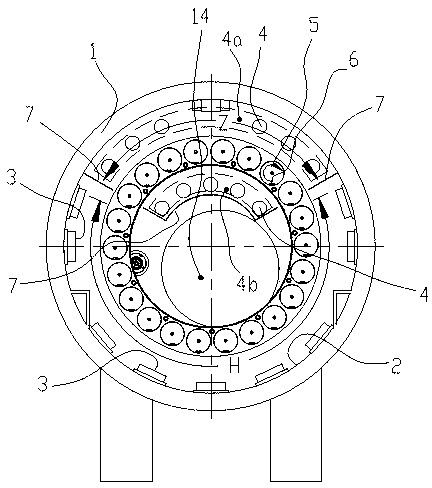
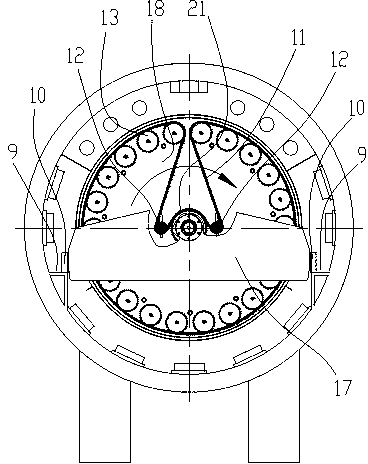
[0026] like figure 1 , figure 2 As shown, the inner wall 2 of the furnace body of the coating machine is divided into two areas, a plurality of arc targets 3 are arranged in area 1 H, and are arranged under the furnace body 1 of the coating machine, and a plurality of sputtering targets 4 are arranged in area 2 Z, and are arranged in the coating machine The top of furnace body 1.

[0027] The sputtering target 4 is a cylindrical structure and can rotate around the axis of the cylinder.

[0028] The sputtering targets 4 are divided into two groups arranged oppositely, one group of sputtering targets 4a is close to the inner wall 2 of the furnace body of the coating machine, and the other group of sputtering targets 4b is set on the coating machine corresponding to the hollow position of the workpiece holder 22 above the center of the coating machine f...


PUM


Abstract

A horizontal type multi-target vacuum sputtering or ion plating machine comprises a plating machine furnace body, a transmission output component in the plating machine, arc-shaped targets, sputtering targets, a vacuum pump-out slot and a workpiece rack, wherein the interior of the plating machine furnace body is divided into two areas, a plurality of arc-shaped targets are distributed in the area I and arranged below the plating machine furnace body and close to the inner wall of the plating machine furnace body, a plurality of sputtering targets are distributed in the area II and arranged above in the inner cavity of the plating machine furnace body at a hollow position of the corresponding workpiece rack above the center of the plating machine furnace body, a rotating part for placing workpieces and a power input mechanism are arranged on the workpiece rack, when the workpiece rack enters the plating machine furnace body, the rotating part can pass through between the arc-shaped targets and the sputtering targets, the power input mechanism of the workpiece rack and the transmission output component in the plating machine are coupled so as to drive the rotating part to rotate, and the vacuum pump-out slot is arranged at the center or close to the center of the plating machine furnace body. According to the horizontal type multi-target vacuum sputtering or ion plating machine, the mutual pollution of the arc-shaped targets and the sputtering targets can be effectively prevented, and the plating efficiency and the plating quality can be improved.

Description

technical field [0001] The invention relates to the technical field of vacuum coating, in particular to a horizontal multi-target vacuum sputtering or ion coating machine for partially replacing the electroplating process. Background technique [0002] Electroplating has been used in industry for a long time, but due to the serious environmental pollution caused by the discharge of three wastes in the electroplating process, a large amount of investment is required to treat it and it is difficult to cure it. It is the vertical multi-target vacuum sputtering or ion coating machine that has been developed rapidly. It is mainly used for rack plating. Its disadvantage is that it is more suitable for the coating of specific workpieces. Realize the effect of barrel plating on the workpiece. [0003] Horizontal multi-target vacuum sputtering or ion coating machines are currently under accelerated development, mainly used for barrel plating small workpieces, such as screws, nuts, p...

Claims


Application Information

Patent Timeline
Patent Type & Authority Applications(China)
IPC IPC(8): C23C14/34
Inventor 周小平翁惠军杨庆忠
Owner 宁波韵升装备技术有限公司
Why Eureka
Try Eureka