
Magnetic suspension vibration isolation platform

A vibration isolation platform and magnetic levitation technology, applied in non-rotation vibration suppression and other directions, can solve the problems of no fixed frequency and active vibration isolation, and achieve the effect of good vibration isolation effect, simple structure and easy control.

Active Publication Date: 2013-09-11
HARBIN INST OF TECH
View PDF4 Cites 18 Cited by
  • Summary
  • Abstract
  • Description
  • Claims
  • Application Information

AI Technical Summary

Problems solved by technology

[0005] In order to overcome the shortcomings of the existing natural frequency in the existing vibration isolation platform, the present invention proposes a magnetic suspension vibration isolation platform without fixed frequency and active vibration isolation

Method used


Image

  • Magnetic suspension vibration isolation platform
  • Magnetic suspension vibration isolation platform
  • Magnetic suspension vibration isolation platform

Examples


specific Embodiment approach 1

[0056] Specific Embodiments 1. The magnetic suspension vibration isolation platform described in this embodiment is composed of a moving base plate, a fixed base plate, n static load-bearing units, i Z-direction adjustment units, j X-direction adjustment units, and j Y-direction adjustment units. n and i are natural numbers greater than or equal to 3, and j is a natural number greater than or equal to 2; the static load-bearing unit, Z-direction adjustment unit, X-direction adjustment unit and Y-direction adjustment unit are symmetrically arranged on the moving base plate and the fixed axis along the X-direction or Y-direction Between the substrates; the Z-direction adjustment unit is mainly composed of a Z-direction actuator, a Z-direction unit controller and a Z-direction sensor, and the X-direction adjustment unit is mainly composed of an X-direction actuator, an X-direction unit controller and an X-direction sensor. The Y-direction adjustment unit is mainly composed of a Y-...

specific Embodiment approach 2

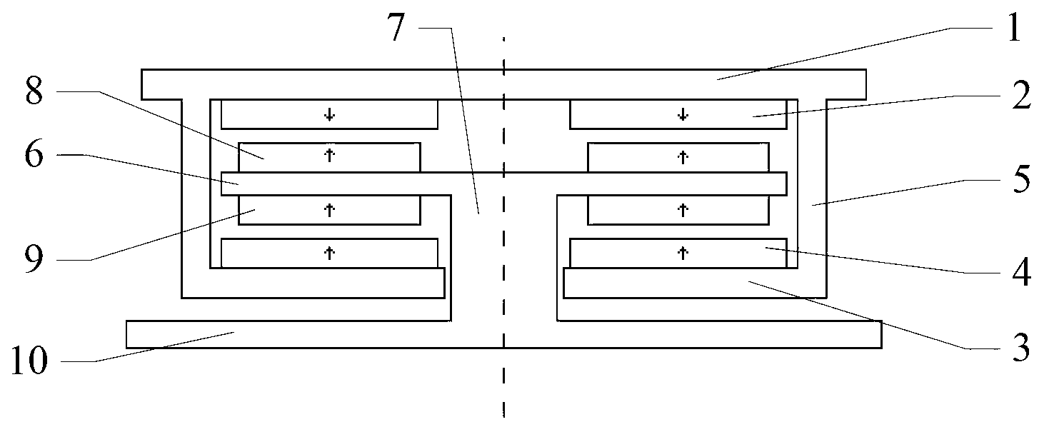
[0062] Specific Embodiment 2. The static load-bearing unit of the magnetic suspension vibration isolation platform described in this embodiment includes a static load-bearing unit mover and a static load-bearing unit stator, and the static load-bearing unit mover includes a first excitation component, a load-bearing platform 1 and a load-bearing support frame, the first excitation component is fixed below the load-bearing platform through the load-bearing support frame, and the permanent magnet in the first excitation component is magnetized in parallel in the vertical direction;

[0063] The static load-bearing unit stator includes a second excitation component, a support base 10 and a support frame, the second excitation component is fixed above the support base through the support frame, and the permanent magnets in the second excitation component are magnetized in parallel in the vertical direction;

[0064] The first excitation part and the second excitation part correspon...

specific Embodiment approach 3

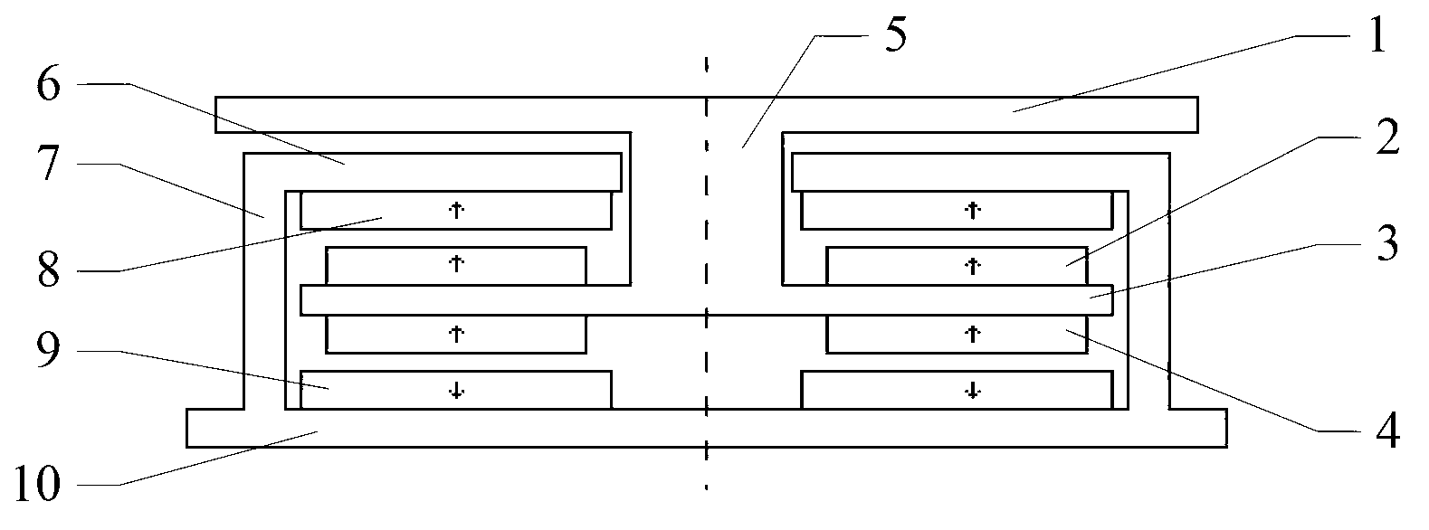
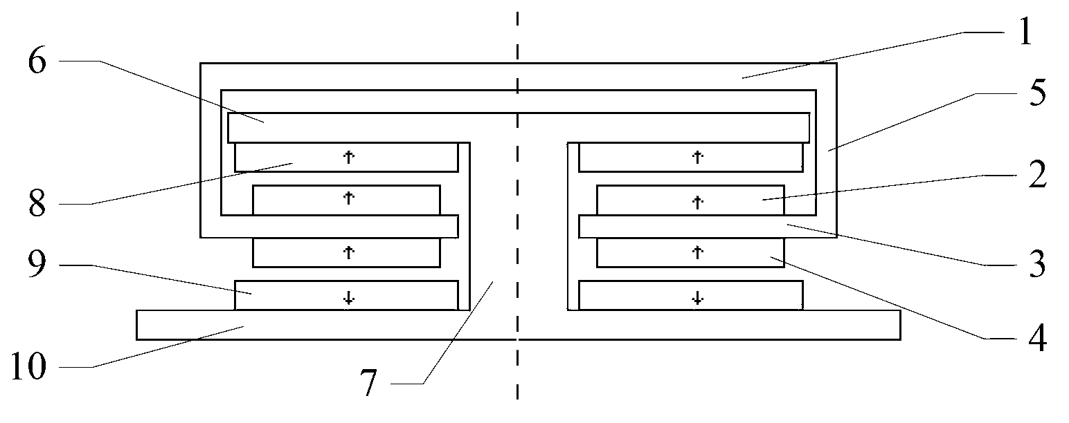
[0066] Specific implementation mode three, see figure 1 This embodiment will be described. This embodiment is a further limitation on the structure of the first excitation component and the second excitation component used in the magnetic suspension vibration isolation platform described in the first embodiment. In this embodiment, the first excitation component includes a first excitation The permanent magnet 2 on the part and the permanent magnet 4 under the first excitation part, the load-bearing support frame is composed of the permanent magnet fixing plate 3 of the first excitation part and the load-bearing support column 5, the permanent magnet 4 under the first excitation part and the first excitation part The upper permanent magnets 2 have the same shape and are all ring-shaped. The upper permanent magnet 2 of the first excitation part and the lower permanent magnet 4 of the first excitation part are symmetrically pasted and fixed on the upper surface and the lower sur...


PUM


Abstract

The invention provides a magnetic suspension vibration isolation platform, and relates to the technical field of magnetic suspension vibration isolation platforms. The magnetic suspension vibration isolation platform overcomes the defect that an existing vibration isolation platform has inherent frequency. The magnetic suspension vibration isolation platform comprises a moving substrate, a fixed substrate, n static state load-bearing units, i Z-direction adjusting units, j X-direction adjusting units and j Y-direction adjusting units, wherein the static state load-bearing units, the X-direction adjusting units, the Y-direction adjusting units and the Z-direction adjusting units are symmetrically arranged between the moving substrate and the fixed substrate along the X-direction axis or the Y-direction axis; each X-direction adjusting unit or each Y-direction adjusting unit or each Z-direction adjusting unit is provided with a unit controller and a sensor correspondingly, and the unit controllers output control signals to the adjusting units; runners of the static state load-bearing units, runners of the X-direction adjusting units, runners of the Y-direction adjusting units and runners of the Z-direction adjusting units are fixed to the bottom face of the moving substrate, stators of the static state load-bearing units, stators of the X-direction adjusting units, stators of the Y-direction adjusting units and stators of the Z-direction adjusting units are fixed to the upper face of the fixed substrate, the plane where the moving substrate is located and the plane where the fixed substrate is located is parallel with each other, and an air gap is formed between the two planes. The magnetic suspension vibration isolation platform is low in rigidity, high in vibration isolation precision, and capable of being applied to a vacuum environment.

Description

technical field [0001] The invention relates to the technical field of magnetic suspension vibration isolation platforms. Background technique [0002] With the continuous development of science and technology, in some technical fields, such as aerospace, and precision optical systems, the processing accuracy of some key parts is required to be higher and higher, thus requiring precision and ultra-precision processing technology. In precision and ultra-precision machining, the accuracy of the equipment itself is of course crucial, but the impact of environmental vibration on machining accuracy and surface quality cannot be ignored. Environmental vibration will not only cause the vibration of the machine tool body, but more importantly, it will generate relative vibration displacement between the cutting tool and the workpiece to be processed, which will be directly reflected on the precision and surface quality of the processed parts. Therefore, it is very necessary to set ...

Claims


Application Information

Patent Timeline
Patent Type & Authority Applications(China)
IPC IPC(8): F16F15/02F16F15/03
Inventor 寇宝泉周一恒张鲁张赫罗俊
Owner HARBIN INST OF TECH
Learn More