Magnetic lock control ball valve

A ball valve and magnetic technology, applied in the field of magnetic lock control ball valve, can solve the problems of accidental opening, misappropriation of gas, gas leakage, etc., and achieve the effect of preventing accidental opening, preventing misappropriation, and simple structure

Inactive Publication Date: 2013-09-11
宁波世亚燃气仪表管件有限公司
View PDF5 Cites 10 Cited by
  • Summary
  • Abstract
  • Description
  • Claims
  • Application Information

AI Technical Summary

Problems solved by technology

When in use, by turning the handle on the valve, the valve rod and the valve core are driven to close or open the flow passage in the valve body. However, when the valve in the prior art is applied to a gas pipeline, the handle on the valve Anyone can operate it simply and freely, especially when the valve is set as the main valve of the gas pipeline, it is easy for people to open the valve to steal gas, thus causing economic losses to the owner
In addition, this type of valve is easy to accidentally open without paying attention, which will cause gas leakage and pose a threat to human safety.

Method used


Image

  • Magnetic lock control ball valve

Examples


Embodiment 1

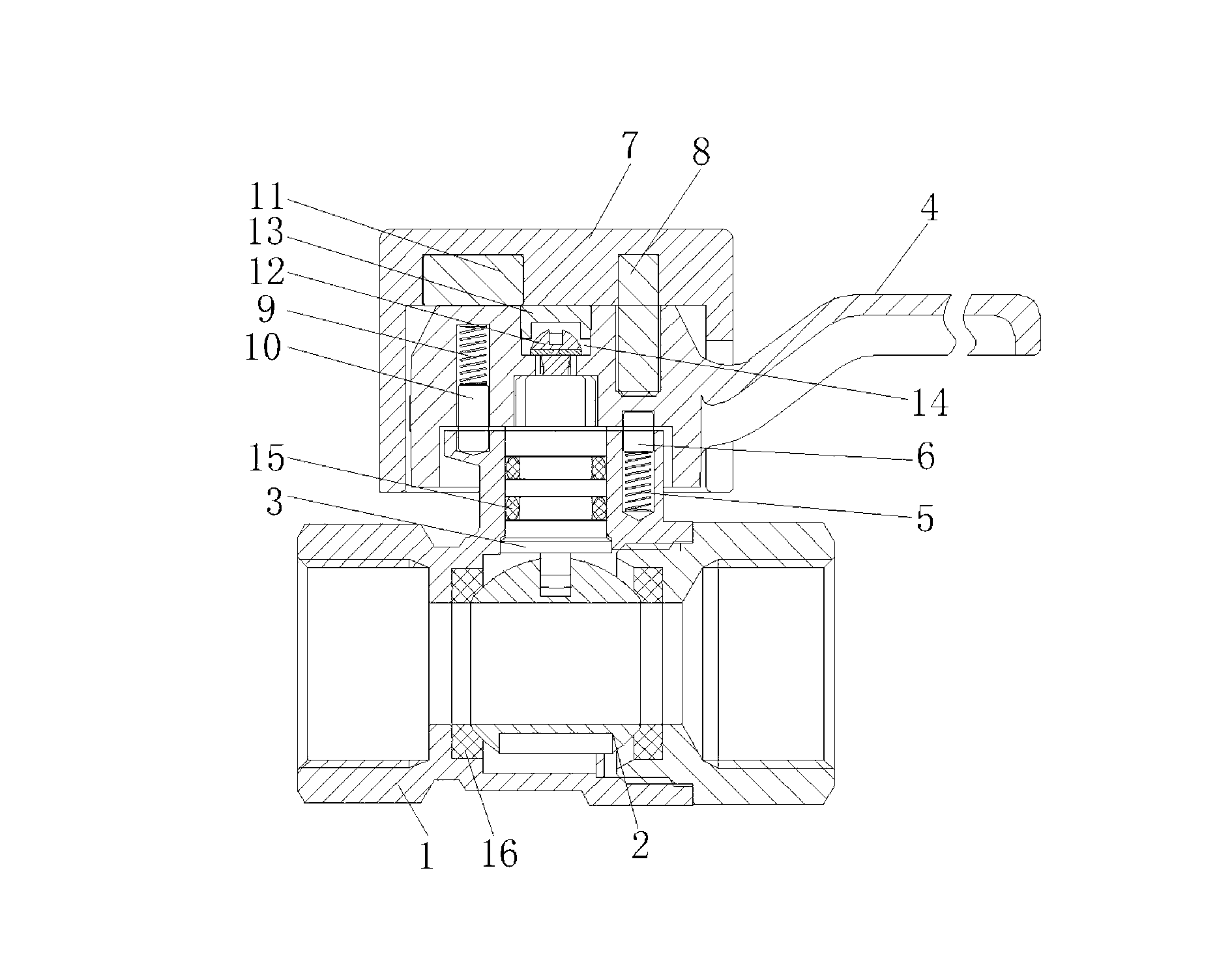
[0021] Such as figure 1 As shown, a magnetic lock control ball valve includes a valve body 1, a ball 2 is arranged inside the valve body 1, a valve stem 3 is connected to the upper end of the ball 2, and a handle 4 is connected to the upper end of the valve stem 3, and the valve body 1 is covered with The upper part of the valve stem 3 is provided with a first blind hole, the first blind hole is provided with a first spring 5, and the lower end of the handle 4 is provided with a second blind hole corresponding to the first blind hole, and the second blind hole is connected to the first blind hole. A first strong magnet 6 is provided between the springs 5, a third blind hole is provided on the top of the handle 4, a lock cap 7 is provided on the handle 4, and a lock cap 7 is provided with one end inserted into the third blind hole. The second strong magnet 8, when the valve needs to be opened, the lock cap 7 is based on the second strong magnet 8, and the lock cap 7 is covered ...

Embodiment 2

[0026] In this embodiment, the upper part of the valve body 1 is provided with a fourth blind hole on the side symmetrical to the first blind hole, and the lower part of the handle 4 is provided with a fifth blind hole corresponding to the fourth blind hole. A second spring 9 is arranged in the blind hole, a positioning pin 10 is arranged between the second spring 9 and the fourth blind hole, and a third strong magnet 11 corresponding to the positioning pin 10 is arranged in the lock cap 7. In this implementation Example can be used alone or in combination with Embodiment 1. When used alone, when the valve needs to be opened, the lock cap 7 is covered on the upper end of the handle 4, and the third strong magnet 11 moves the positioning pin 10 upward under the action of the magnetic force to release the positioning. The pin 10 blocks the handle 4, so that the handle 4 can be pulled. When the valve needs to be locked, the handle 4 is moved to a suitable position, and the lock ca...


PUM


Abstract

The invention relates to the technical field of valves, in particular to a magnetic lock control ball valve. The magnetic lock control ball valve comprises a valve body. A ball is disposed in the valve body. A valve rod is connected to the upper end of the ball. A handle is connected to the upper end of the valve rod. A first blind hole is formed in the upper portion of the valve body. A first spring is disposed in the first blind hole. A second blind hole is formed in the lower end of the handle. A first strong magnet is disposed between the second blind hole and the first spring. A third blind hole is formed in the upper portion of the handle. A lock cap is sleeved outside the handle. A second strong magnet is disposed in the lock cap. When the valve needs to be opened, the lock cap is covered at the upper end of the handle, the second strong magnet pushes the first strong magnet downwardly under the action of the spring to relieve the first strong magnet's blocking to the handle, a positioning pin moves upwardly to relieve the positioning pin's blocking to the handle, and the handle can be pulled. When the valve needs to be locked, the lock cap is taken off when the handle is pulled to an appropriate position, the first strong magnet and the positioning pin reset through the spring to limit and lock the handle, and theft and accidental opening can be prevented.

Description

technical field [0001] The invention relates to the technical field of valves, in particular to a magnetic lock control ball valve. Background technique [0002] At present, the valve structure in the prior art generally includes a valve body, a valve core and a valve stem arranged in the valve body. When in use, by turning the handle on the valve, the valve rod and the valve core are driven to close or open the flow passage in the valve body. However, when the valve in the prior art is applied to a gas pipeline, the handle on the valve Anyone can operate simply and arbitrarily, especially when the valve is set as the main valve of the gas pipeline, people are easy to open the valve to embezzle gas, thereby causing economic losses to the owner. In addition, this type of valve is easy to accidentally open without paying attention, which will cause gas leakage and pose a threat to human safety. Contents of the invention [0003] The purpose of the present invention is to p...

Claims


Application Information

Patent Timeline
Patent Type & Authority Applications(China)
IPC IPC(8): F16K35/16F16K5/06
Inventor 龚建军
Owner 宁波世亚燃气仪表管件有限公司
Why Eureka
Try Eureka