Large-size backlight module backboard splicing structure and LCD device

A backlight module, large-scale technology, applied in the direction of lighting devices, lighting auxiliary devices, lighting device components, etc., can solve the problems of backplane pressure resistance and other resistance performance reduction, leakage lock, low production capacity, etc., to achieve screw The effect of reducing the amount of consumables, improving labor efficiency, and shortening assembly time

Active Publication Date: 2013-09-11
TCL CHINA STAR OPTOELECTRONICS TECH CO LTD
View PDF2 Cites 1 Cited by
  • Summary
  • Abstract
  • Description
  • Claims
  • Application Information

AI Technical Summary

Problems solved by technology

[0003] However, the current method of screw-locking flat splicing parts to produce backplanes has the following disadvantages: 1. There are many screw-locks. During the production and installation process, it takes a lot of manual installation, and the mass production is not good. Low; 2. There are many screw holes, which are often prone to missing locks, making the backboard not fast; 3. A lot of screw holes are processed on the backboard, so that the overall pressure resistance and other resistance of the backboard are improved. The reduction is very large, affecting the quality and life of the backplane

Method used


Image

  • Large-size backlight module backboard splicing structure and LCD device
  • Large-size backlight module backboard splicing structure and LCD device
  • Large-size backlight module backboard splicing structure and LCD device

Examples


Embodiment Construction

[0031] It should be understood that the specific embodiments described here are only used to explain the present invention, not to limit the present invention.

[0032] The present invention proposes a large-size backlight module backplane splicing structure.

[0033] refer to figure 1 , figure 1 It is a structural schematic diagram of the first embodiment of the large-size backlight module backplane splicing structure of the present invention.

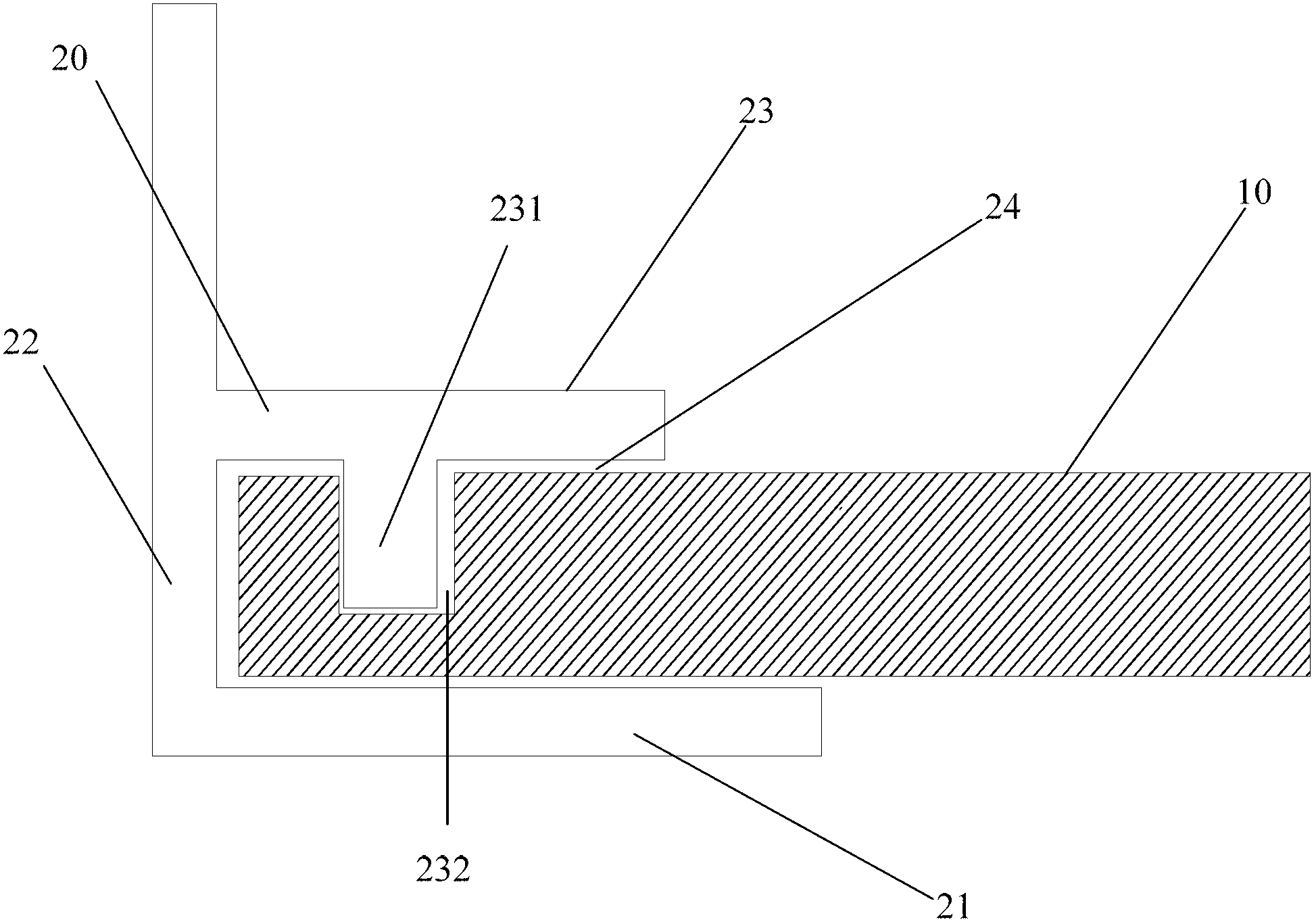
[0034] In the first embodiment of the present invention, the backplane splicing structure of the large-size backlight module, wherein the backplane includes a bottom plate 10 and a splicing piece 20 spliced ​​at the end side of the bottom plate 10;

[0035] The splicing piece 20 comprises a side plate 22, an upper supporting plate 23 and a lower supporting plate 21 which are arranged on the same side of the side plate 22 and are perpendicular to the side plate 22; The lower bottom surface of 23 forms the clamping opening 24 for cla...


PUM


Abstract

The invention discloses a large-size backlight module backboard splicing structure. A backboard includes a bottom flat plate, and a splicing piece spliced on the end side of the bottom flat plate; the splicing piece includes a side plate, as well as an upper support plate and a lower support plate both arranged on the same side of the side plate and vertical to the side plate; the lower bottom surface of the upper support plate, the upper top surface of the lower support plate and the side plate form a clamping mouth used for clamping the bottom flat plate; column groove assembling structures are arranged on the lower bottom surface of the upper support plate and the bottom flat plate; and fastening screws are arranged between the bottom flat plate and the splicing piece. Compared with the mounting manner in the prior art, the large-size backlight module backboard splicing structure provided by the invention has the advantages that fixing in the two-dimensional direction of the three-dimensional direction is realized, fixing in the third-dimensional direction is realized through the several screws, so that the fastened mounting is realized, working procedures are greatly reduced, consumed screws are greatly reduced, the time consumed in the assembly is shortened, and the labor efficiency is greatly improved.

Description

technical field [0001] The invention relates to the technical field of liquid crystal display, in particular to a backplane splicing structure of a large-size backlight module and a liquid crystal display device. Background technique [0002] With the innovation of LCD technology, large-size LCD TVs are becoming more and more mature, and the unit price is getting lower and lower. The technological innovation of large-size backlights has also become a new trend. Most of the existing large-size module backplanes use flat panels. The way of splicing forms a complete backplane. [0003] However, the current method of screw-locking flat splicing parts to produce backplanes has the following disadvantages: 1. There are many screw-locks. During the production and installation process, it takes a lot of manual installation, and the mass production is not good. Low; 2. There are many screw holes, which are often prone to missing locks, making the backboard not fast; 3. A lot of scre...

Claims


Application Information

Patent Timeline
Patent Type & Authority Applications(China)
IPC IPC(8): F21V21/00G02F1/13357
CPCG02F1/133308G02F1/133314
Inventor 郭仪正萧宇均张彦学
Owner TCL CHINA STAR OPTOELECTRONICS TECH CO LTD
Why Eureka
Try Eureka