Gas turbine combustor

A gas turbine and burner technology, which is applied to gas turbine devices, burners, combustion chambers, etc., can solve problems such as poor atomization characteristics, and achieve the effects of promoting atomization and reducing efficiency.

Active Publication Date: 2013-09-11
MITSUBISHI POWER LTD
View PDF11 Cites 5 Cited by
  • Summary
  • Abstract
  • Description
  • Claims
  • Application Information

AI Technical Summary

Problems solved by technology

However, the micronization characteristics are inferior to those of the two-fluid system, and this tendency becomes prominent especially under conditions of low supply pressure.

Method used


Image

  • Gas turbine combustor
  • Gas turbine combustor
  • Gas turbine combustor

Examples


no. 1 approach )

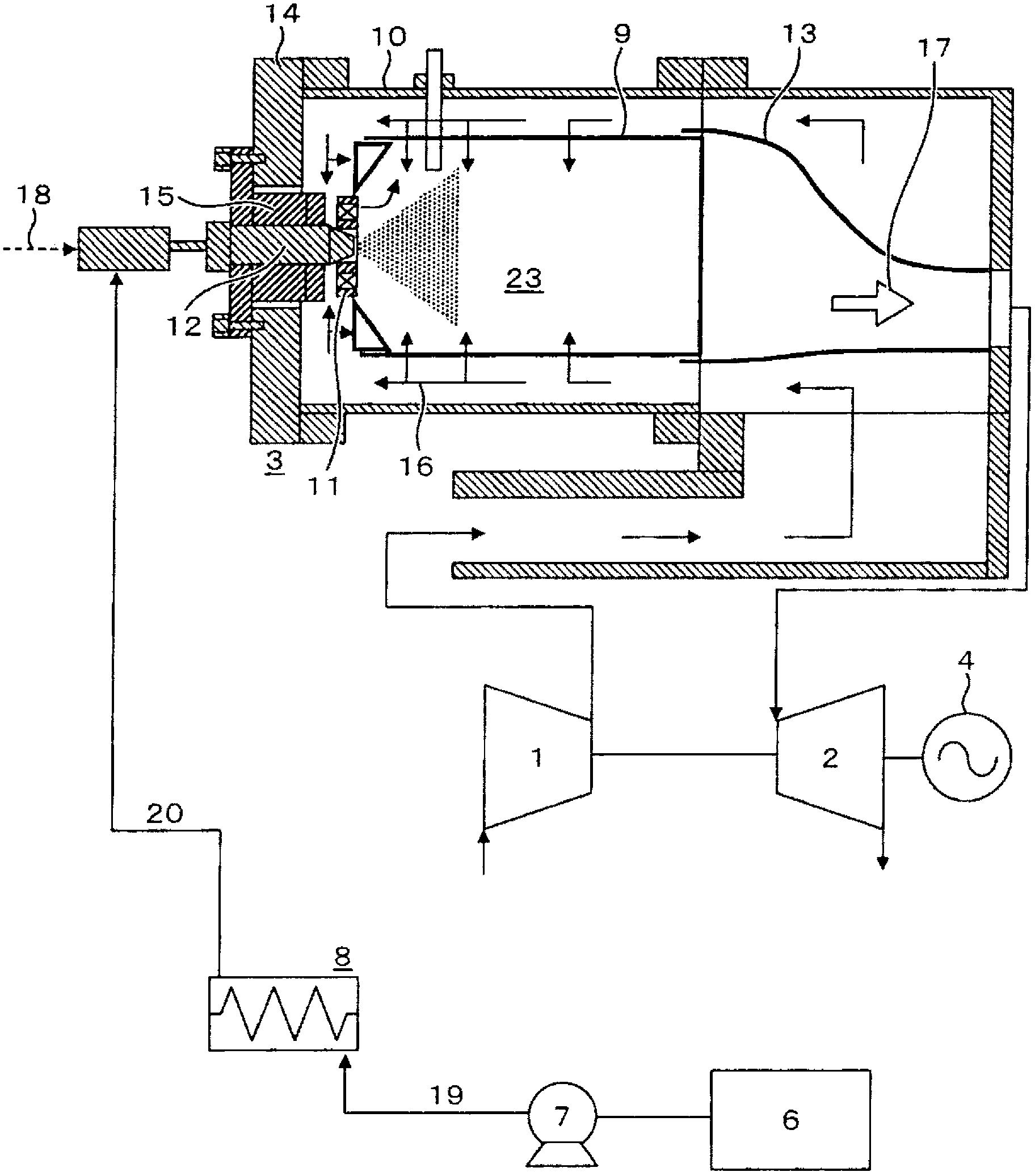
[0027] Refer to the following figure 1 , figure 2 , the first embodiment of the present invention will be described. figure 1 It is a schematic configuration diagram showing the configuration of the first embodiment of the gas turbine combustor according to the present invention in a longitudinal sectional view and schematically showing the overall configuration of a gas turbine device including the gas turbine combustor.

[0028] figure 1 The gas turbine device shown mainly includes: a compressor 1 that compresses air to generate high-pressure combustion air; a combustor 3 that mixes combustion air 16 introduced from the compressor 1 and liquid fossil fuel 18 to generate combustion gas 17; And the turbine 2 that introduces the combustion gas 17 generated by the combustor 3 . In addition, the compressor 1 is connected to the shafts of the turbine 2 and the generator 4 .

[0029] The above-mentioned combustor 3 is composed of the following parts: an inner cylinder 9 formin...

no. 2 approach )

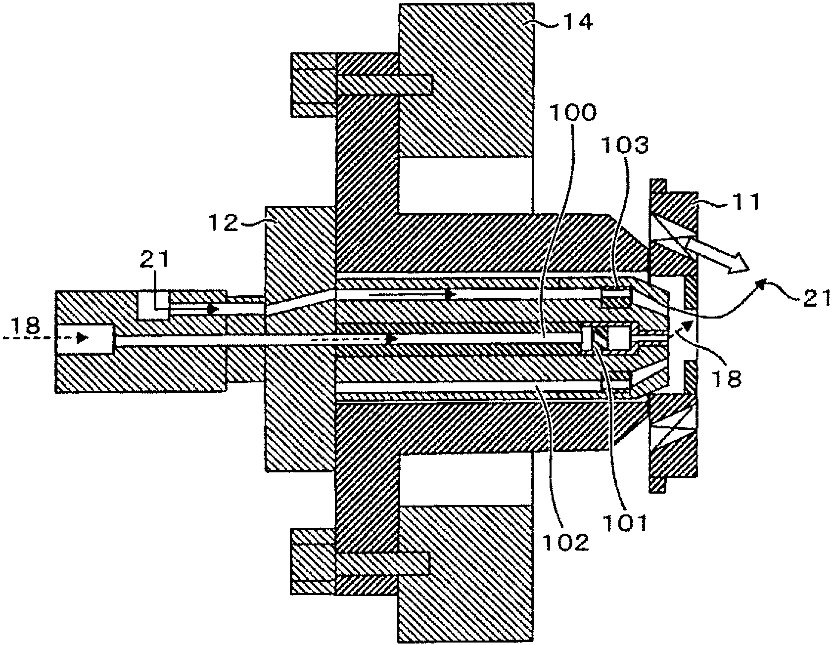
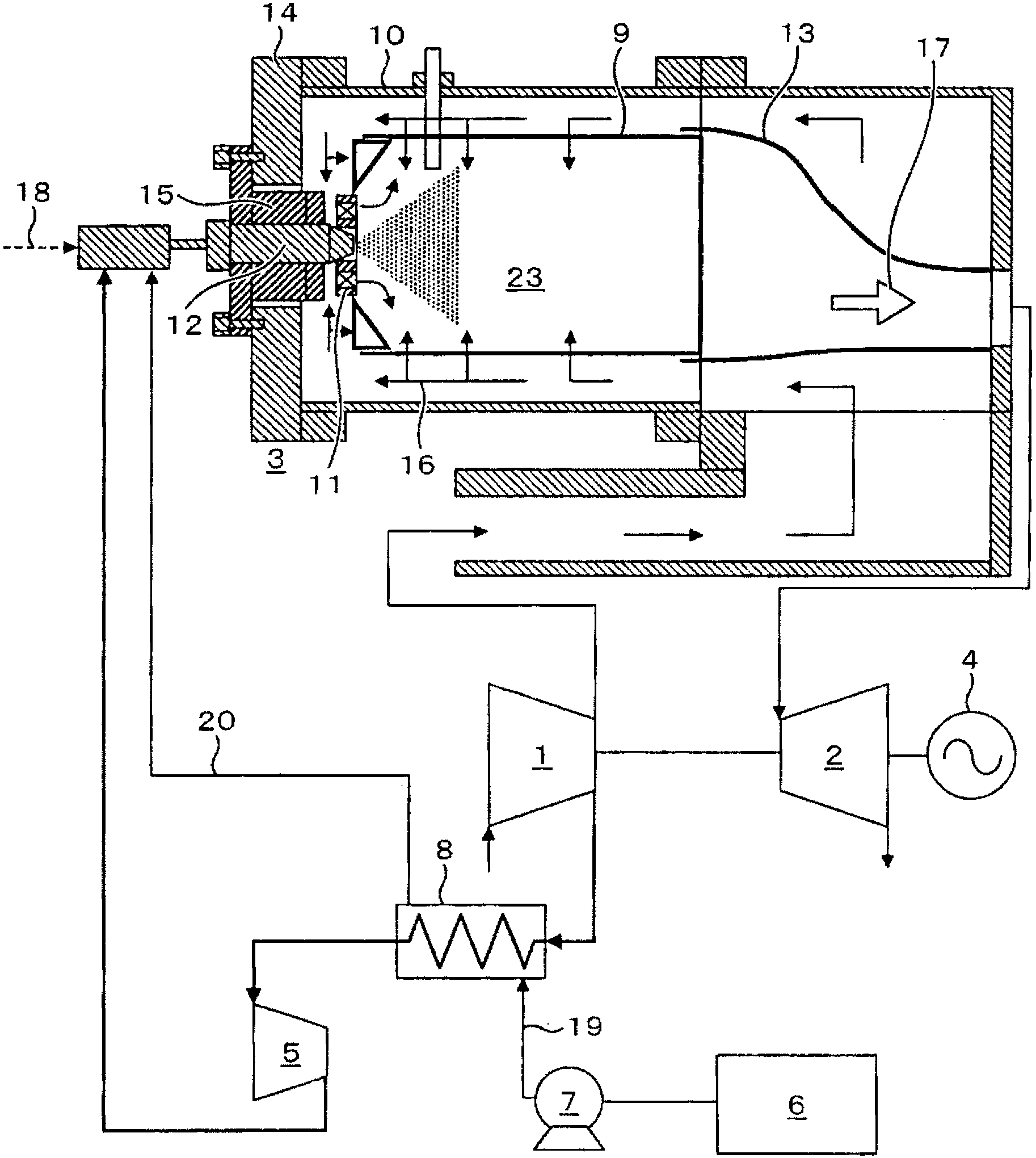
[0041] Refer to the following image 3 , Figure 4 , the second embodiment of the present invention will be described. image 3 It is a schematic configuration diagram showing the configuration of the second embodiment of the gas turbine combustor according to the present invention in a longitudinal sectional view and schematically showing the overall configuration of a gas turbine device including the gas turbine combustor. Figure 4 yes image 3 Partial detailed cross-sectional view of the fuel injection valve 12. The basic structure is the same as that of the first embodiment. This embodiment differs from the first embodiment in that the heat of high-pressure spray air can be used as means for heating a low boiling point liquid fuel (ethanol fuel in this embodiment). and, if Figure 4 As shown, in addition to the liquid fossil fuel system 100 as the first system and the ethanol fuel system 102 as the second system, the fuel injection valve 12 of this embodiment is equi...

no. 3 approach )

[0047] Refer to the following Figure 5 , the third embodiment of the present invention will be described. The basic structure of this embodiment is the same as that of the second embodiment. The present embodiment differs from the second embodiment in that the structure of the injection valve 12 is different. The fuel injection valve 12 of the present embodiment has a discharge hole for injecting liquid fossil fuel 18 formed in the center, a discharge hole for injecting ethanol fuel 21 is formed on its outer periphery, and a discharge hole for injecting spray air 22 is formed on its outer periphery. .

[0048] Generally, the temperature at which a liquid fossil fuel starts to harden by the heat of the surroundings varies depending on the type of fuel. For example, in the case of light oil, the temperature is about 180°C. Therefore, conventionally, from the viewpoint of preventing coking, it was necessary to control the temperature of the high-pressure spray air supplied to...


PUM


Abstract

The present invention provides a gas turbine combustor that has, as means for atomizing liquid fuel, a fuel injection nozzle using a fluid other than liquid fuel to atomize the liquid fuel and that can suppress a reduction in power generation efficiency resulting from a heat loss while promoting the atomization of the liquid fuel. The gas turbine combustor 3 is adapted to mix liquid fuel with combustion air led from a compressor, burn the mixture and supply combustion gas generated to a gas turbine. The gas turbine combustor includes, on the upstream side thereof, a fuel injection nozzle that atomizes the liquid fuel into fine liquid droplets. The fuel injection nozzle includes a first system adapted to supply the liquid fuel and a second system adapted to supply a fluid for atomizing the liquid fuel. Low-boiling liquid fuel is supplied to the second system as the fluid. The second system is adapted to heat and supply the low-boiling liquid fuel.

Description

technical field [0001] The present invention relates to gas turbine combustors. Background technique [0002] Generally, in a combustor that burns liquid fuel, the liquid fuel is atomized from a fuel nozzle, and the mixture of small-diameter fuel droplet groups and fuel air is promoted to be combusted. [0003] There are two types of fuel nozzles for atomizing liquid fuel: a two-fluid type fuel nozzle that uses a medium other than liquid fuel, such as high-pressure air, to atomize the air; A fuel nozzle of a single-fluid type that accelerates the injection velocity of liquid fuel and atomizes it by using a certain supply pressure. [0004] The former two-fluid system is superior in atomization performance compared to the single-fluid system, and is effective in suppressing the emission of smoke, which is one of the problems of a burner burning liquid fuel. However, since air for atomization is required, for example, in the case of suction from a compressor of a gas turbine...

Claims


Application Information

Patent Timeline
Patent Type & Authority Applications(China)
IPC IPC(8): F23R3/00F23R3/28
CPCF23R3/30F23D11/107F23D11/22F02C7/00
Inventor 平田义隆高桥宏和关口达也小泉浩美吉田正平笹尾俊文林明典
Owner MITSUBISHI POWER LTD
Why Eureka
Try Eureka