Heat storage and exchange method used for recovering waste heat of smoke with flying ash

A flue gas waste heat and heat method technology, which is applied in the field of flue gas waste heat recovery, can solve problems such as deposition, blockage, and regenerator inoperability, and achieve the effects of simple structural design and operation, and low ash removal costs

Inactive Publication Date: 2013-09-11
SHANGHAI JIAO TONG UNIV
View PDF7 Cites 3 Cited by
  • Summary
  • Abstract
  • Description
  • Claims
  • Application Information

AI Technical Summary

Problems solved by technology

But the defect and deficiency of this prior art compared with the present invention are: when gas contains more fly ash, after flowing through checker brick and pebble bed described in this prior art, fly ash can be deposited in checker brick aperture And in the pebble bed, if it is serious, it will cause blockage, so that the regenerator cannot work, and the furnace needs to be frequently shut down for cleaning

Method used


Image

  • Heat storage and exchange method used for recovering waste heat of smoke with flying ash
  • Heat storage and exchange method used for recovering waste heat of smoke with flying ash
  • Heat storage and exchange method used for recovering waste heat of smoke with flying ash

Examples


Embodiment 1

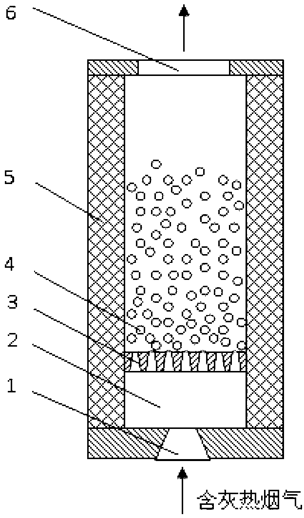
[0037] Such as figure 1 As shown, the method of this embodiment is as follows: first, before the flue gas containing fly ash enters the regenerator, reduce the fly ash entering the regenerator; secondly, accelerate the travel speed of the flue gas, and the flue gas enters the regenerator The refractory ball 4 bed is blown to increase the gap between the refractory ball 4, and the refractory ball 4 bed forms a fluidized bed, and the heat exchange between the flue gas and the refractory ball 4 makes the heat stored in the In the refractory ball 4, the fly ash entering the regenerator flows out of the regenerator, so as to avoid blocking the circulation channel.

[0038] The way to reduce the fly ash entering the regenerator is: install an air chamber 2 before the regenerator, and at the same time, install an air distribution plate 3 at the entrance of the regenerator, when the flue gas containing fly ash enters the air chamber 2 And when it flows through the air distribution pl...

Embodiment 2

[0056] This embodiment is a device based on the method of Embodiment 1, such as figure 1 As shown, it includes: regenerator, air chamber 2, air distribution plate 3 and refractory ball 4, wherein: the entrance of the regenerator is provided with an air distribution plate 3, the front is provided with an air chamber 2, and the circulation channel of the regenerator There are refractory balls 4 in it.

[0057] The air inlet of the air chamber 2 is provided with a nozzle, and the structure of the nozzle is a trapezoidal structure with a wide inlet at the bottom and a narrow outlet at the top.

[0058] Evenly have some through-holes on the described air distribution plate 3, the structure of this through-hole is the trapezoidal structure that bottom entrance is wide and top exit is narrow.

[0059] The outside of the heat storage chamber is provided with an insulating layer 5 .

[0060] The flue gas containing fly ash enters the air chamber 2 from the nozzle 1, and after being u...


PUM


Abstract

The invention discloses a heat storage and exchange method used for recovering waste heat of smoke with flying ash. Before the smoke with the flying ash enters a heat storage room, a wind room is arranged to reduce the amount of flying ash entering the heat storage room, the wind inlet of the wind room is provided with a spraying pipe to accelerate traveling of the smoke, the smoke enters a fire-proof ball bed layer of the heat storage room and blows fire-proof balls to increase the gaps among the fire-proof balls, the fire-proof ball bed layer forms a fluidized bed, heat exchange is conducted between the smoke and each fire-proof ball to ensure that heat is stored in the fire-proof balls, the flying ash entering the heat storage room flows out the heat storage room, and therefore a flowing channel is prevented from being blocked. The heat storage and exchange method used for recovering the waste heat of the smoke with the flying ash is simple in structure, design and operation, low in ash removing cost, and particularly suitable for occasions where the ash content of smoke is high.

Description

technical field [0001] The invention relates to a method in the technical field of waste heat recovery from flue gas, in particular to a heat storage and heat exchange method for recovering waste heat from flue gas containing fly ash. Background technique [0002] High-temperature air combustion technology is widely used in metallurgy, machinery, chemical industry, solid waste treatment and other fields. It has the advantages of uniform combustion / heating, high thermal efficiency, NO x The advantages of low emissions. The core component of this technology is the heat storage and heat exchange device, which adopts fast reversing operation, which can greatly recover the heat of high-temperature flue gas and use it to preheat combustion-supporting gas and fuel. The heat storage and heat exchange device is equipped with two or more paired regenerators, which are filled with randomly piled refractory balls or directly use refractory honeycomb to store or release heat in the form...

Claims


Application Information

Patent Timeline
Patent Type & Authority Applications(China)
IPC IPC(8): F27D17/00
CPCY02P10/25Y02P80/15
Inventor 于娟
Owner SHANGHAI JIAO TONG UNIV
Why Eureka
Try Eureka