Blue phase liquid crystal display device capable of achieving visual angle controllable characteristic and transflective characteristic

A blue-phase liquid crystal and display device technology, which is applied in nonlinear optics, instruments, optics, etc., can solve the problems of not achieving color timing display, and achieve the effect of reducing driving difficulty and manufacturing difficulty

Active Publication Date: 2013-09-11
HEBEI UNIV OF TECH
View PDF6 Cites 16 Cited by
  • Summary
  • Abstract
  • Description
  • Claims
  • Application Information

AI Technical Summary

Problems solved by technology

However, this technology requires liquid crystal displays to have a faster response speed, and the corresponding speed of most common nematic liquid crystal displays is 10ms, which cannot meet the requirements of color sequential display.

Method used


Image

  • Blue phase liquid crystal display device capable of achieving visual angle controllable characteristic and transflective characteristic
  • Blue phase liquid crystal display device capable of achieving visual angle controllable characteristic and transflective characteristic
  • Blue phase liquid crystal display device capable of achieving visual angle controllable characteristic and transflective characteristic

Examples


Embodiment 1

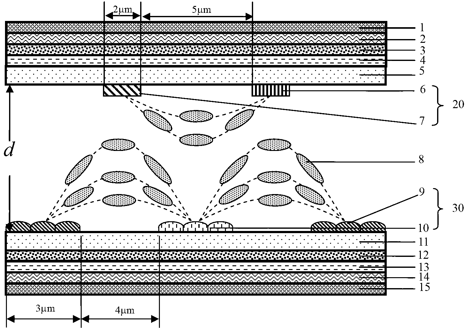
[0031] figure 1 It is a schematic structural diagram of a blue-phase liquid crystal display device that can realize controllable viewing angle and transflective display according to the patent of the present invention. The device includes from top to bottom: upper polarizer 1, upper λ / 4 biaxial film 2, upper λ / 2 Negative A plate 3, upper λ / 4 positive A plate 4, upper substrate 5, upper substrate IPS electrode 20, blue phase liquid crystal 8, lower substrate IPS electrode 30, lower substrate 11, lower λ / 4 negative A plate 12, lower λ / 2 positive A plate 13 , lower λ / 4 biaxial film 14 and lower polarizing plate 15 . Among them: the upper substrate IPS electrode 20 is an ITO electrode, located on the lower surface of the upper substrate 5, including the upper substrate Pixel electrode 6 and the upper substrate Common electrode 7, arranged at intervals; the lower substrate IPS electrode 30 is an aluminum electrode, and its position is located at intervals. Right below the gap bet...

Embodiment 2

[0053] Figure 5 It is a schematic structural diagram of a blue-phase liquid crystal display device that can realize controllable viewing angle and transflective display according to the patent of the present invention. The device includes from top to bottom: upper polarizer 1, upper λ / 4 biaxial film 2, upper λ / 2 Negative A plate 3, upper λ / 4 positive A plate 4, upper substrate 5, upper substrate IPS electrode 20, blue phase liquid crystal 8, lower substrate IPS electrode 30, lower substrate 11, lower λ / 4 negative A plate 12, lower λ / 2 positive A plate 13 , lower λ / 4 biaxial film 14 and lower polarizing plate 15 . Among them: the upper substrate IPS electrode 20 is an ITO electrode, located on the lower surface of the upper substrate 5, including the upper substrate Pixel electrode 6 and the upper substrate Common electrode 7, arranged at intervals; the lower substrate IPS electrode 30 is an aluminum electrode, located on the lower substrate 11 The surface, including the Pix...


PUM

PropertyMeasurementUnit
porosityaaaaaaaaaa
porosityaaaaaaaaaa
thicknessaaaaaaaaaa

Abstract

The invention provides a blue phase liquid crystal display device capable of achieving a visual angle controllable characteristic and a transflective characteristic. The device sequentially comprises an upper Polaroid, an upper lambda/4 double-shaft film, an upper lambda/2 negative A piece, an upper lambda/4 positive A piece, an upper substrate, an upper substrate IPS electrode, blue phase crystals, a lower substrate IPS electrode, a lower substrate, a lower lambda/4 negative A piece, a lower lambda/2 positive A piece, a lower lambda/4 double-shaft film and a lower Polaroid from top to bottom, wherein the upper substrate IPS electrode is an ITO electrode which comprises an upper substrate Pixel electrode and an upper substrate Common electrode, and the lower substrate IPS electrode is an aluminum electrode which comprises a lower substrate Pixel electrode and a lower substrate Common electrode. The box thickness of a transflective area is the same as the box thickness of a reflecting area, manufacturing difficulties are greatly reduced, meanwhile, the transflective area and the reflecting area have the same phase delay, driving can be conducted through a single gamma curve, driving difficulties are reduced, and meanwhile dual display characteristics, namely, the visual angle controllable characteristic and the transflective characteristic, are achieved.

Description

technical field [0001] The invention designs a device in the technical field of liquid crystal display, specifically a blue-phase liquid crystal display device capable of realizing transflective display and display with controllable viewing angle. Background technique [0002] Transflective liquid crystal displays are widely used in mobile display devices due to their features such as sunlight readability and low power consumption. In order to meet the readability in sunlight, single-cell thick liquid crystal displays and double-cell thick liquid crystal displays have been proposed, and the former is more favored by manufacturers because of its simple manufacturing process. However, it is more difficult for a single-cell thick liquid crystal display to achieve phase delay matching between the transmissive area and the reflective area, because the backlight source passes through the transmissive area once, while the ambient light passes through the reflective area twice. At ...

Claims


Application Information

Patent Timeline
Patent Type & Authority Applications(China)
IPC IPC(8): G02F1/1343G02F1/137
Inventor 孙玉宝栗鹏赵彦礼李岩峰
Owner HEBEI UNIV OF TECH
Why Eureka
Try Eureka