
Cross-power spectrum based blind source separation method

A cross-power spectrum and blind source separation technology, applied in the field of blind source separation, can solve the problems of high-speed calculation difficulties, lack of portability, and inability to effectively describe the time-varying characteristics of signals, and achieve good experimental results

Inactive Publication Date: 2013-09-11
TIANJIN UNIVERSITY OF TECHNOLOGY
View PDF2 Cites 12 Cited by
  • Summary
  • Abstract
  • Description
  • Claims
  • Application Information

AI Technical Summary

Problems solved by technology

When a non-stationary signal is input, the diversity of signal characteristics leads to different applications, the algorithm structure is very different, and there is no portability. These characteristics have brought great difficulties to the current high-speed calculation of ICA. At the same time, the general deterministic blind source separation The effect is not good for the separation of non-stationary signals, and cannot effectively describe the time-varying characteristics of the signal, thus restricting the blind source separation performance of time-varying signals

Method used


Image

  • Cross-power spectrum based blind source separation method
  • Cross-power spectrum based blind source separation method
  • Cross-power spectrum based blind source separation method

Examples


Embodiment 1

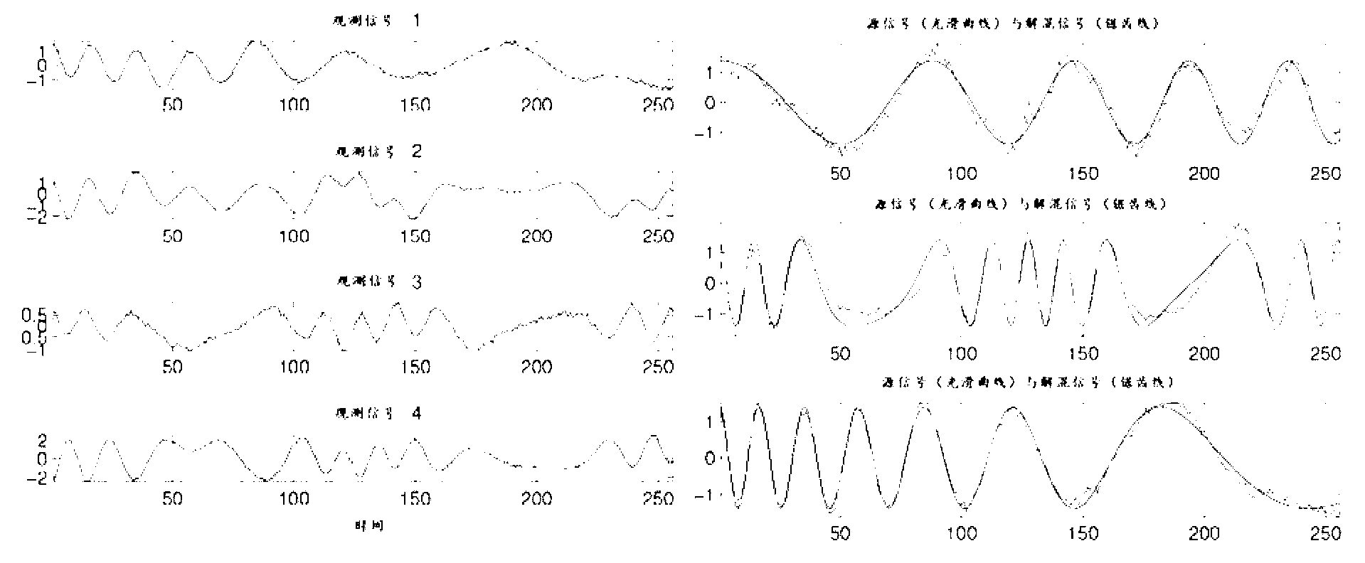
[0047] figure 1 An example of blind source separation for a multi-channel mixed signal, figure 1 On the left is the observed signal X, figure 1 The smooth curve on the right is the true source signal Z' and the sawtooth curve is the calculated estimated signal Z.

[0048] In order to test the validity in the experiment, where the source signal represents Z'=[s 1 ;s 2 ;s 3 ], that is, the following three source signals, t=1,...,256 in the experiment.

[0049] the s 1 (t)=cos(0.00024414t 2 +0.05t)

[0050] the s 2 (t)=cos(4.13sin(0.0154πt)+0.25t)

[0051] the s 3 (t)=cos(0.0000017872t 3 -0.0014t 2 +0.4027t)

[0052] The observed signal X is generated by multiplying the following random matrix with Z'.

[0053] 0.4119 - 0.0695 1.2778 - 0.5296 0.8313 ...

Embodiment 2

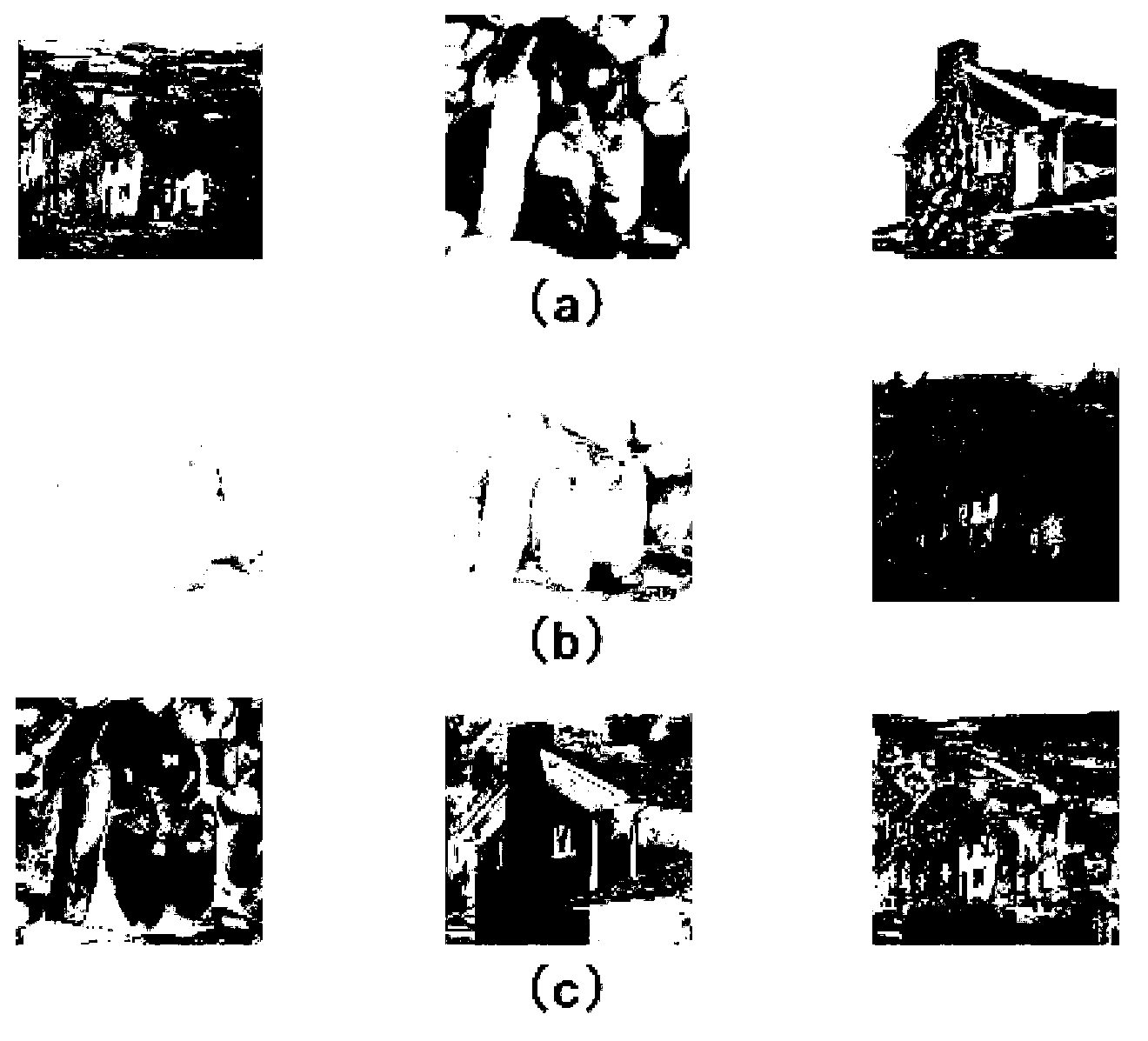
[0078] figure 2 For an example of blind source separation for mixed images, figure 2 a is the source image Z' before mixing, figure 2 b is the observed mixed image X, that is, the original image is mixed by the following matrix.

[0079] The three images selected in the experiment, such as figure 2 As shown in a, the size of each image is 256×256 pixels, and each image is converted into a 1-dimensional signal s with a length of 256×256=65536 during mixing i (i=1,2,3), then the source signal represents Z'=[s 1 ;s 2 ;s 3 ], the source signals are mixed in the following matrix.

[0080] 0.6991 0.9012 0.8445 0.2454 0.7209 0.6812 0.4458 0.2279 0.1275 ...


PUM


Abstract

The invention provides a cross-power spectrum based blind source separation method aiming at an existing blind source separation method and particularly at time-frequency variations under the circumstance of non-stable mixed signals. The method includes firstly, whitening input signals; secondly, computing power spectrums and cross-power spectrums of received whitened mixed signals or mixed images by the aid of a lag autocorrelation method; thirdly, organizing a power spectrum and a cross-power spectrum of each sampling point to construct a cross-power spectrum matrix, and separating a cross-power spectrum matrix of the mixed signals or mixed images by a joint diagonalization mode to obtain separated matrixes; and finally, utilizing the obtained separated matrixes for separating observed mixed image signals to achieve the purpose for blind source separation of the signals or images. The blind source separation method achieves satisfactory signal separation effect under the circumference of non-stable mixed signal mixing, and has important applications in radio communication systems and audio frequency and acoustic and medical signal processing in the industrial and military fields.

Description

technical field [0001] The invention belongs to the technical field of signal processing and relates to a blind source separation method, which can be widely used in industrial control or communication processing. Background technique [0002] In real life and nature, it is very difficult to obtain a real and original source signal that reflects a certain physical characteristic. The information obtained by the sensor is often a signal mixed with multiple unknown signal components. The purpose of processing the observed signal is to recover the unknown Individual raw source signals that are directly observed. The process of blind source separation can be described as: by looking for a full-rank linear transformation matrix, in order to make each component of the output as independent as possible, and to approximate each source signal to the greatest extent. [0003] Now the main method of linear and nonlinear instantaneous mixing in blind source separation is the Jacobi met...

Claims


Application Information

Patent Timeline
Patent Type & Authority Applications(China)
IPC IPC(8): G06T5/00
Inventor 王京辉赵源超
Owner TIANJIN UNIVERSITY OF TECHNOLOGY
Learn More