Pneumatically-driven double-end automatic crimping device

A technology of pneumatic drive and crimping device, which is applied in the direction of connection, electrical components, circuits, etc., can solve the problems of high labor intensity, affect the appearance, and slow speed, and achieve the effect of improving crimping efficiency, simple structure, and solving interference

Inactive Publication Date: 2013-09-11
BEIJING UNIV OF TECH
View PDF9 Cites 5 Cited by
  • Summary
  • Abstract
  • Description
  • Claims
  • Application Information

AI Technical Summary

Problems solved by technology

The conductor connection here, that is, the connection between the MiniSeal crimping tube and the wire needs to be completed by the crimping force generated by the crimping device. At present, manual crimping pliers are widely used for double-ended crimping. The operation process is cumbersome. First, insert the wire into the MiniSeal In the hole on one side of the butt joint, use a manual pliers tool to crimp, then reverse the crimping direction, insert the wire into the other side of the MiniSeal butt joint, and then use a manual pliers to crimp
Manual crimping is heavy work, labor-intensive, slow, and inefficient. Also, because the two ends of the terminal are crimped separately, the crimping surfaces on both sides of the terminal cannot be guaranteed to be consistent, which affects the appearance. It can be seen that it is necessary to realize double-ended crimping automation.
In a device for automatic double-end crimping of butt terminals, the manual crimping pliers is used as the base, and a motion actuator is installed on the arm of the crimping pliers to realize automatic crimping. However, there is currently no effective way to realize automatic crimping of butt terminal terminals. Executive device

Method used


Image

  • Pneumatically-driven double-end automatic crimping device
  • Pneumatically-driven double-end automatic crimping device
  • Pneumatically-driven double-end automatic crimping device

Examples


Embodiment Construction

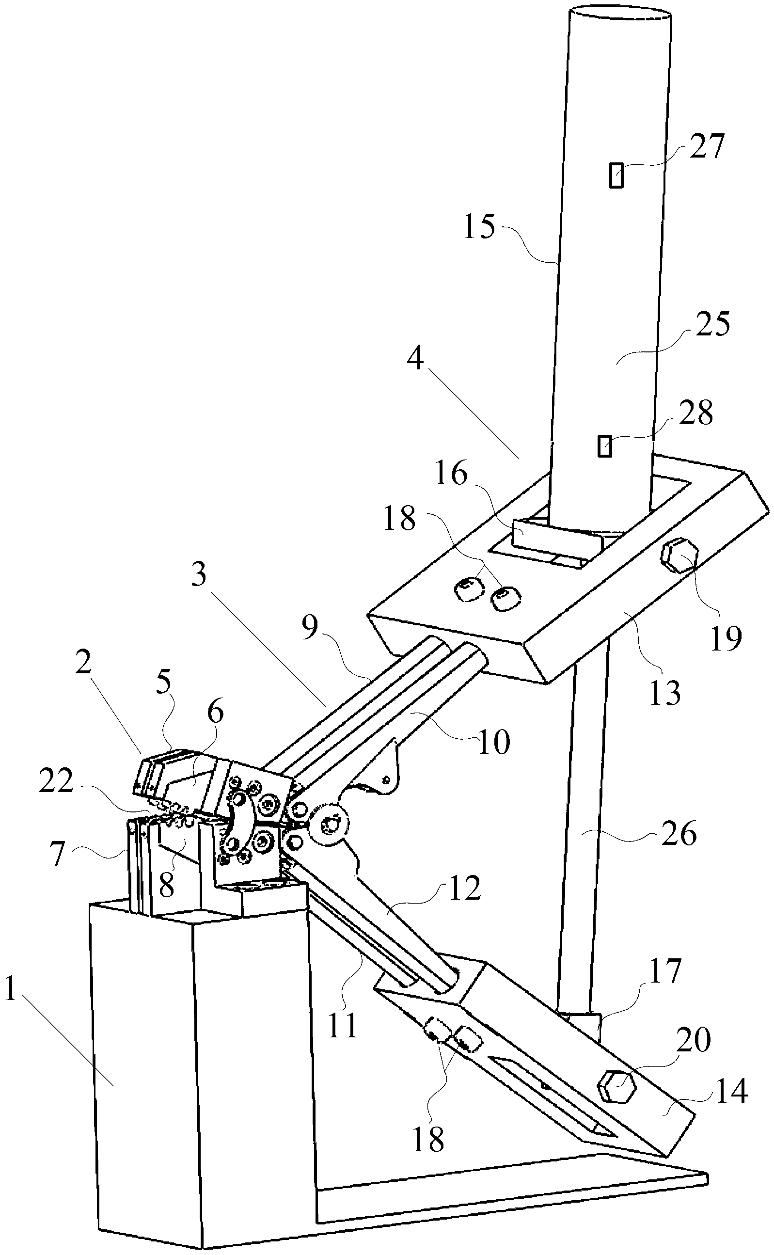
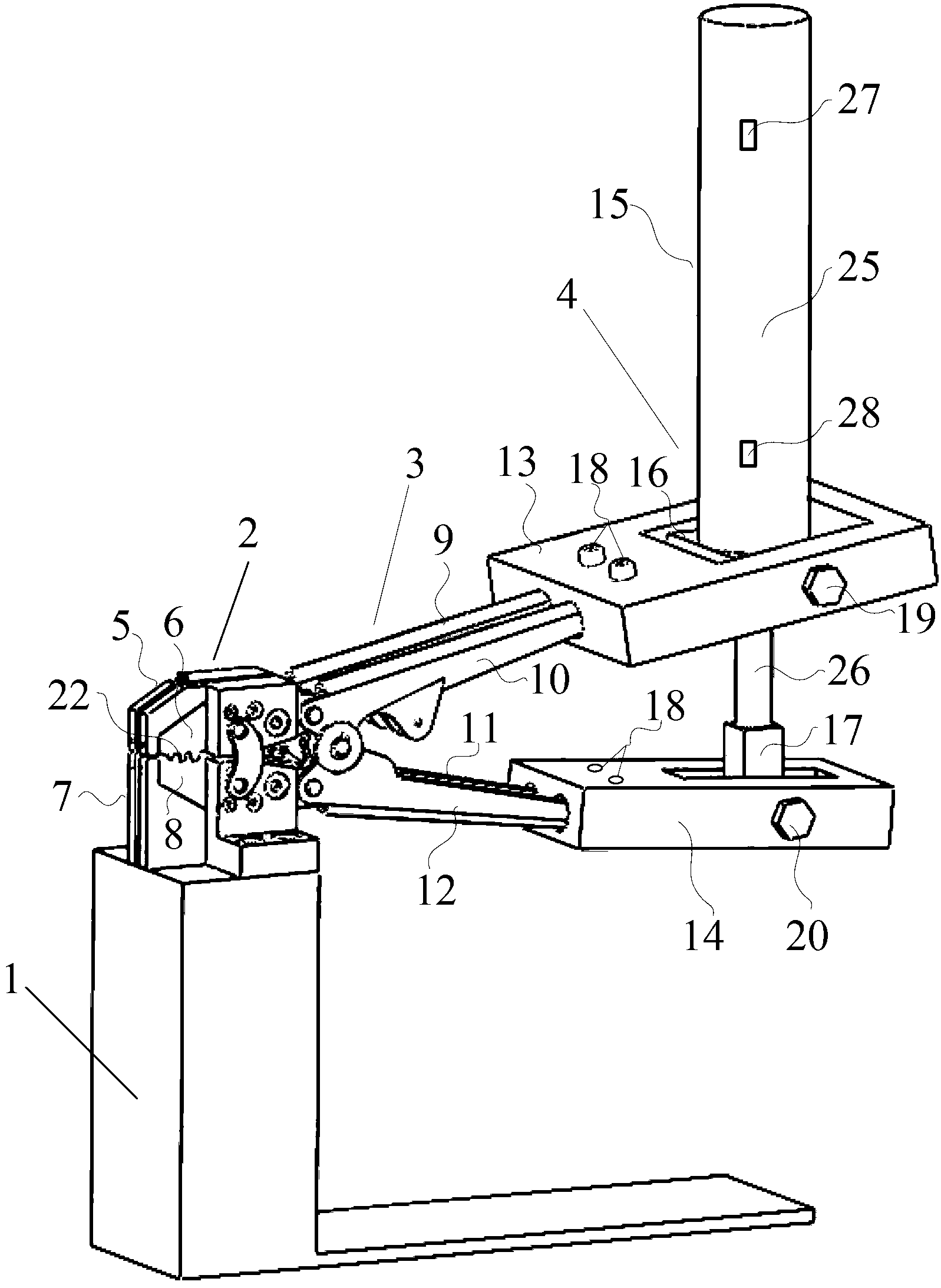
[0017] The process of double-ended terminal crimping is simply to put the two ends of the double-ended terminal through the wires for crimping. Such as figure 1 As shown, the device of the present invention includes a base 1, a clamp assembly 2, a clamp arm assembly 3 and a pneumatic device 4; the clamp assembly 2 is fixed on the base 1, its rear end is connected with the clamp arm assembly 3, and the pneumatic device 4 is installed on the clamp After the arm assembly 3, it exerts force on the pliers arm assembly 3 to realize automatic crimping.

[0018] The initial state of the double-ended automatic crimping device is as follows figure 1 Shown, this moment press clamp jaw 22 opens fully, at first, will Figure 4 The butt joint terminal shown is placed on the jaws 22 of the pliers, and the wires are respectively penetrated to both ends of the butt terminal; after the threading is in place, the crimping action is performed: the cylinder 15 is driven to retract the piston rod...


PUM


Abstract

The invention belongs to the field of electrical tools, and relates to a pneumatically-driven double-end automatic crimping device which aims at threading leads into two ends of a butt joint terminal to perform crimping to enable the butt joint terminal to be reliably connected with the lead. In order to realize double-end crimping automation, the pneumatically-driven double-end automatic crimping device comprises a pressing pliers assembly, a pliers arm assembly and a pneumatic device, pliers arms are connected with a cylinder in a hinged manner by the aid of pin connection, coordinated changing between a forced direction and a movement direction is realized, the problem of interference of the forced direction and the movement direction in a fixed connection manner is solved effectively, and opening and closing of a pressing pliers jaw are achieved accurately by arrangement of magnetic switches. The pneumatically-driven double-end automatic crimping device is simple in structure and low in cost, a manual crimping mode is substituted, automation of double-end crimping is realized, and crimping efficiency is improved greatly.

Description

technical field [0001] The invention belongs to the field of electrical tools, and relates to a device for automatically crimping a conductive wire and a coaxial butt terminal. The crimping device generates a crimping force, and the two ends of the butt terminal can be reliably connected to the wire by means of the crimping force. The double-ended automatic crimping device can replace the widely used manual crimping pliers at present, and has the advantages of high operating efficiency, firm crimping, and good appearance quality. Background technique [0002] MiniSeal coaxial butt joint terminal is a tinned copper alloy shielded wire joint, which is used in conjunction with a transparent heat-shrinkable sleeve, and is widely used in the connection of shielded cables including coaxial cables and multi-core cables. The conductor connection here, that is, the connection between the MiniSeal crimping tube and the wire needs to be completed by the crimping force generated by the ...

Claims


Application Information

Patent Timeline
Patent Type & Authority Applications(China)
IPC IPC(8): H01R43/048
Inventor 王新华高燕龚志奔涂承媛孙树文郑刚
Owner BEIJING UNIV OF TECH
Why Eureka
Try Eureka