Composite-structure bearingless switched reluctance motor and control method thereof

A technology of switched reluctance motor and composite structure, which is applied in the direction of electrical components, magnetic attraction or thrust holding device, etc., to achieve the effect of simple control method, small influence and high power density

Inactive Publication Date: 2013-09-11
NANJING UNIV OF AERONAUTICS & ASTRONAUTICS
View PDF2 Cites 28 Cited by
  • Summary
  • Abstract
  • Description
  • Claims
  • Application Information

AI Technical Summary

Problems solved by technology

[0004] The purpose of the present invention is to propose a control method for a switched reluctance motor with a composite rotor structure, in order to solve the problem of decoupling the levitation force and torque, and then to take advantage of the high-speed adaptability and high power density characteristics of the bearingless switched reluctance motor

Method used


Image

  • Composite-structure bearingless switched reluctance motor and control method thereof
  • Composite-structure bearingless switched reluctance motor and control method thereof
  • Composite-structure bearingless switched reluctance motor and control method thereof

Examples


Embodiment Construction

[0019] Below in conjunction with accompanying drawing, a kind of composite structure bearingless switched reluctance motor proposed by the present invention and its control method are further specifically described:

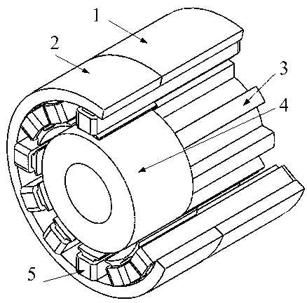
[0020] like figure 1 Shown: a composite structure bearingless switched reluctance motor, including a torque stator, a levitation force stator, a torque rotor, a levitation force rotor and windings; the torque stator and the levitation force stator are axially stacked together to form a For the stator, when superimposed, the centers of the two stator teeth are aligned, and the number of teeth of the two stators is 12; one winding is wound on the stator teeth, and the torque stator and the suspension force stator share one winding, and the winding form adopts a concentrated winding; each The windings on the 4 stator teeth separated by 90° are one-phase windings, that is, each phase winding has 4 windings, of which there are two windings in the α-axis direction and ...


PUM


Abstract

The invention relates to a composite-structure bearingless switched reluctance motor and a control method thereof and belongs to the field of bearingless switched reluctance motors and control methods thereof. A torque stator and a levitation stator are axially stacked to form a stator; a winding is wound on teeth of the stator and passes the torque stator and the levitation stator, and the winding is wound in a central winding manner; a rotor comprises a torque rotor and a levitation rotor, the torque rotor and the levitation rotor are axially stacked in the stator, the torque rotor is located below the torque stator, the torque stator and the torque rotor are equal in axial length, and the levitation stator corresponds to the levitation rotor while the levitation stator and the levitation rotor are equal in axial length; the levitation stator is in a pole shoe structure, and the polar arc angle of the levitation stator is larger than that of the torque stator. Levitation and torque decoupled control is achieved; the control method is simple; radial bearing force is large; the motor is fine in levitating performance. Levitation control is achieved by minimum inductance zone; the levitating current has low effect on torque current, and interphase coupling effect is low.

Description

technical field [0001] The invention relates to a composite structure bearingless switched reluctance motor and a control method thereof, belonging to the field of bearingless switched reluctance motors and the control method thereof. Background technique [0002] The bearingless switched reluctance motor is a new type of magnetic levitation motor developed at the end of the 20th century. The double-winding bearingless switched reluctance motor is to stack the levitation winding that generates the levitation force and the winding of the original ordinary switched reluctance motor on the stator of the motor. By controlling the current of the two sets of windings, it has the ability to rotate and self-levitate at the same time So as to realize the ultra-high speed operation of the motor. The single-winding bearingless switched reluctance motor controls the current of each set of windings independently through distribution so that it has the ability to rotate and self-suspend ...

Claims


Application Information

Patent Timeline
Patent Type & Authority Applications(China)
IPC IPC(8): H02N15/00
Inventor 刘泽远邓智泉曹鑫杨燕
Owner NANJING UNIV OF AERONAUTICS & ASTRONAUTICS
Why Eureka
Try Eureka