
Wire harness and method of manufacturing wire harness

A wire harness, longitudinal direction technology, applied in the field of wire harnesses, can solve problems such as contact or deformation of metal protection tubes, and achieve the effect of reducing costs

Active Publication Date: 2015-11-25
YAZAKI CORP
View PDF6 Cites 0 Cited by
  • Summary
  • Abstract
  • Description
  • Claims
  • Application Information

AI Technical Summary

Problems solved by technology

[0009] In the above-mentioned related art, there is a problem that, when transporting the wire harness, in order to prevent the metal protection tubes from coming into contact with each other or deforming, it is necessary to secure enough space for each metal protection tube and each wire harness

Method used


Image

  • Wire harness and method of manufacturing wire harness
  • Wire harness and method of manufacturing wire harness
  • Wire harness and method of manufacturing wire harness

Examples


Embodiment

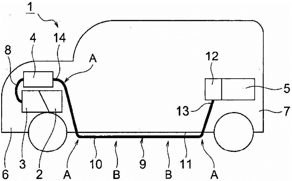
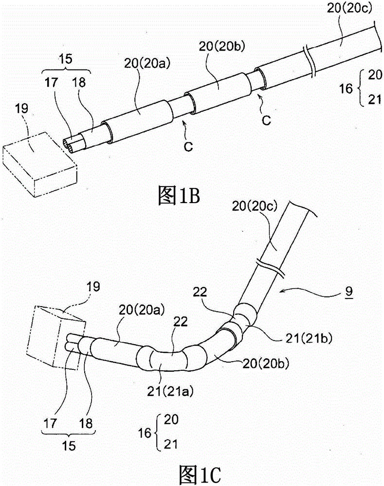
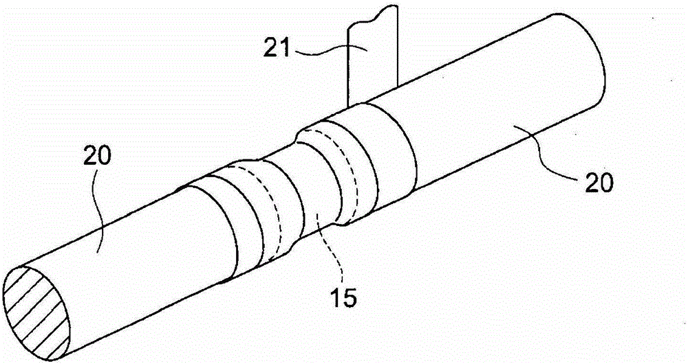
[0070] Hereinafter, an embodiment will be described with reference to the drawings. Figure 1A to Figure 1C is an illustration of the wire harness according to this embodiment. Figure 2A to Figure 2C is a diagram showing a photocrosslinkable fixing member. Figure 3A and Figure 3B is a schematic representation of another example according to the previous exterior part and photocrosslinkable fixation part. In this embodiment, a description will be given based on an example of the wire harness of the present invention employed in a hybrid motor vehicle (also in an electric vehicle).

[0071] exist Figure 1A Among them, the hybrid motor vehicle 1 is a vehicle in which the power of the engine 2 and the motor unit 3 are mixed and the vehicle is driven. Electric power is supplied from a battery 5 (battery pack) to the motor unit 3 via the inverter unit 4 . In this embodiment, the engine 2, the motor unit 3 and the inverter unit 4 are installed in the engine room 6 where the f...


PUM


Abstract

A wire harness includes: one or more conductive paths; and an outer member that includes a plurality of leading outer members, each having a tubular shape that passes along the one or more conductive paths; and a watercrosslinkable fixing member or a photocrosslinkable fixing member that bonds adjacent leading outer members of the plurality of leading outer members which are separate away from each other in a longitudinal direction of the one or more conductive paths.

Description

technical field [0001] The present invention relates to a wire harness including one or more conductive paths and an outer member covering the conductive paths and a method of manufacturing the same. Background technique [0002] The wire harness disclosed in Patent Document 1 includes: three high-voltage cables, and three metal protection tubes that house and protect the three respective high-voltage cables. A high voltage cable is provided to connect the motor installed at the front of the vehicle to the inverter installed at the middle or rear of the vehicle. [0003] The wire harness is routed through the floor body of the vehicle outside the vehicle frame. Therefore, a metal protective tube is formed to protect the high voltage cable from bouncing off stones or splashing water. The metal protection tube has rigidity to protect the high-voltage cable from bouncing off stones or splashing water and prevents the high-voltage cable from bending. Since the metal protectio...

Claims


Application Information

Patent Timeline
Patent Type & Authority Patents(China)
IPC IPC(8): B60R16/02F16L7/00F16L7/02
CPCH02G3/0406B60R16/0207B60R16/0215H02G3/0641
Inventor 远山荣一
Owner YAZAKI CORP
Learn More