Actuator driving apparatus
A technology of driving device and actuator, applied in the direction of transducer head device, driving/moving recording head, instrument, etc., can solve the problem of high power consumption of D/A converter, etc.
- Summary
- Abstract
- Description
- Claims
- Application Information
AI Technical Summary
Problems solved by technology
Method used
Image

Examples
no. 1 Embodiment approach
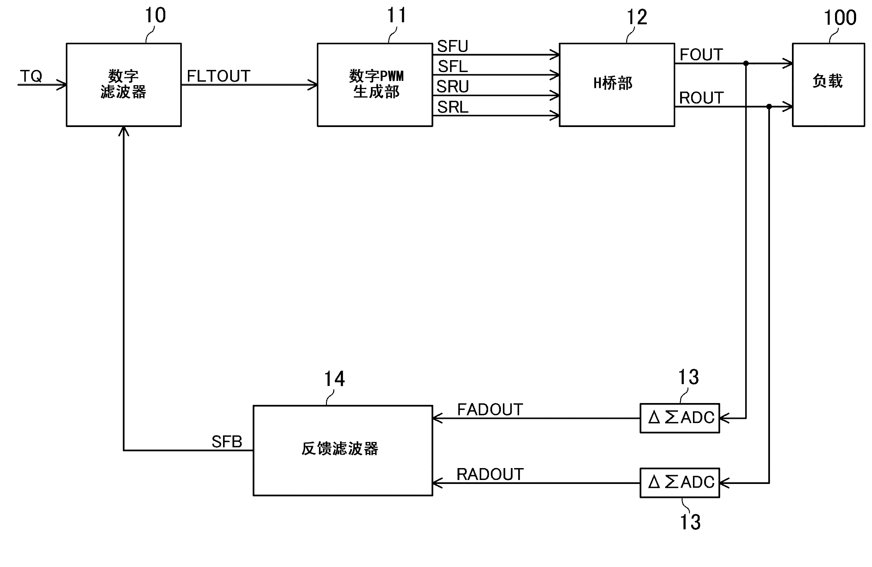
[0045] figure 1 The configuration of the actuator driving device according to the first embodiment is shown. The load 100 to be driven by the actuator driving device according to the present embodiment is, for example, a voice coil motor or the like which is a part of the actuator not shown. When the F terminal voltage FOUT is applied to the load 100, a forward current flows through the load 100, and the actuator moves in the forward direction. On the other hand, when the R terminal voltage ROUT is applied to the load 100, a reverse current flows through the load 100, and the actuator moves in the reverse direction. And, the torque generated in the actuator varies according to the amount of current supplied to the load 100 . That is, if more current is supplied to the load 100, a greater torque is generated in the actuator.
[0046] The actuator drive device according to this embodiment performs output switching and PWM control of FOUT and ROUT based on a torque command dig...
no. 2 Embodiment approach
[0118] Figure 17 The configuration of the actuator drive device according to the second embodiment is shown. The actuator drive device according to the present embodiment has an error integrating unit 16 added to the actuator drive device according to the first embodiment.
[0119] The error integration unit 16 corrects FLTOUT by adding a value obtained by integrating errors of TQ and SFB to FLTOUT output from the digital filter 10 .
[0120] The digital PWM generator 11 outputs SFU, SFL, SRU, and SRL based on the corrected FLTOUT. Specifically, the digital PWM generator 11 determines which of SFU, SFL, SRU, and SRL should be controlled according to the positive and negative polarities of the corrected FLTOUT for each PWM period, and further, according to the corrected The absolute value of FLTOUT determines the timing of edge generation of the signal to be controlled.
[0121] Configurations and operations other than those described above are the same as those described i...
no. 3 Embodiment approach
[0124] Figure 18 The configuration of the actuator driving device according to the third embodiment is shown. The actuator driving device according to the present embodiment has a guard detection unit 17 added to the actuator driving device according to the first embodiment.
[0125] If the load 100 is continuously driven in a state where a power supply fault or an earth fault has occurred at the output of the actuator driving device, the transistors constituting the H-bridge portion 12 may be destroyed by an abnormal voltage. . Therefore, in order to protect the H bridge portion 12 from being damaged, the protection detection portion 17 checks whether FOUT and ROUT are correctly output according to the control of the digital PWM generation portion 11, and if an incorrect output is detected, the actuator driving device will be activated. Output stops.
[0126] Specifically, the feedback filter 14 is Figure 16 In the case of the configuration shown in (a), if the protecti...
PUM
 Abstract
Description
Claims
Application Information
 - R&D Engineer
- R&D Manager
- IP Professional
- Industry Leading Data Capabilities
- Powerful AI technology
- Patent DNA Extraction
Browse by: Latest US Patents, China's latest patents, Technical Efficacy Thesaurus, Application Domain, Technology Topic.
© 2024 PatSnap. All rights reserved.Legal|Privacy policy|Modern Slavery Act Transparency Statement|Sitemap