
Anterior cervical interbody fusion cage

An intervertebral fusion cage and anterior cervical spine technology, applied in the direction of fixator, internal fixator, internal bone synthesis, etc., can solve the problems of increasing the risk of surgical failure, damaging the cage, affecting observation, etc., to facilitate imaging observation. , The effect of human implantation is safe and conducive to fusion

Inactive Publication Date: 2013-09-18
广州聚生生物科技有限公司
View PDF10 Cites 16 Cited by
  • Summary
  • Abstract
  • Description
  • Claims
  • Application Information

AI Technical Summary

Problems solved by technology

For example, the patent number is ZL02276208.6, and the utility model patent named intervertebral fusion device is made of DL-lactic acid, poly-L-lactic acid and copolymer; Intervertebral fusion cage installation equipment, because the fusion cage is subjected to external percussion force and friction between the upper and lower vertebral bodies, and the strength of the material itself is limited, it is easy to damage the fusion cage, increasing the risk of surgical failure
[0005] In the utility model patent with the announcement number CN201701334U and the name of cervical spine fusion device, titanium alloy material is used, but because the elastic modulus of titanium alloy material is much larger than that of human bone, stress shielding occurs, according to woff's law, it may form false The phenomenon of joint or non-fusion; and artifacts will appear during X-ray and CT examinations, which will affect postoperative observation

Method used


Image

  • Anterior cervical interbody fusion cage
  • Anterior cervical interbody fusion cage
  • Anterior cervical interbody fusion cage

Examples


Embodiment

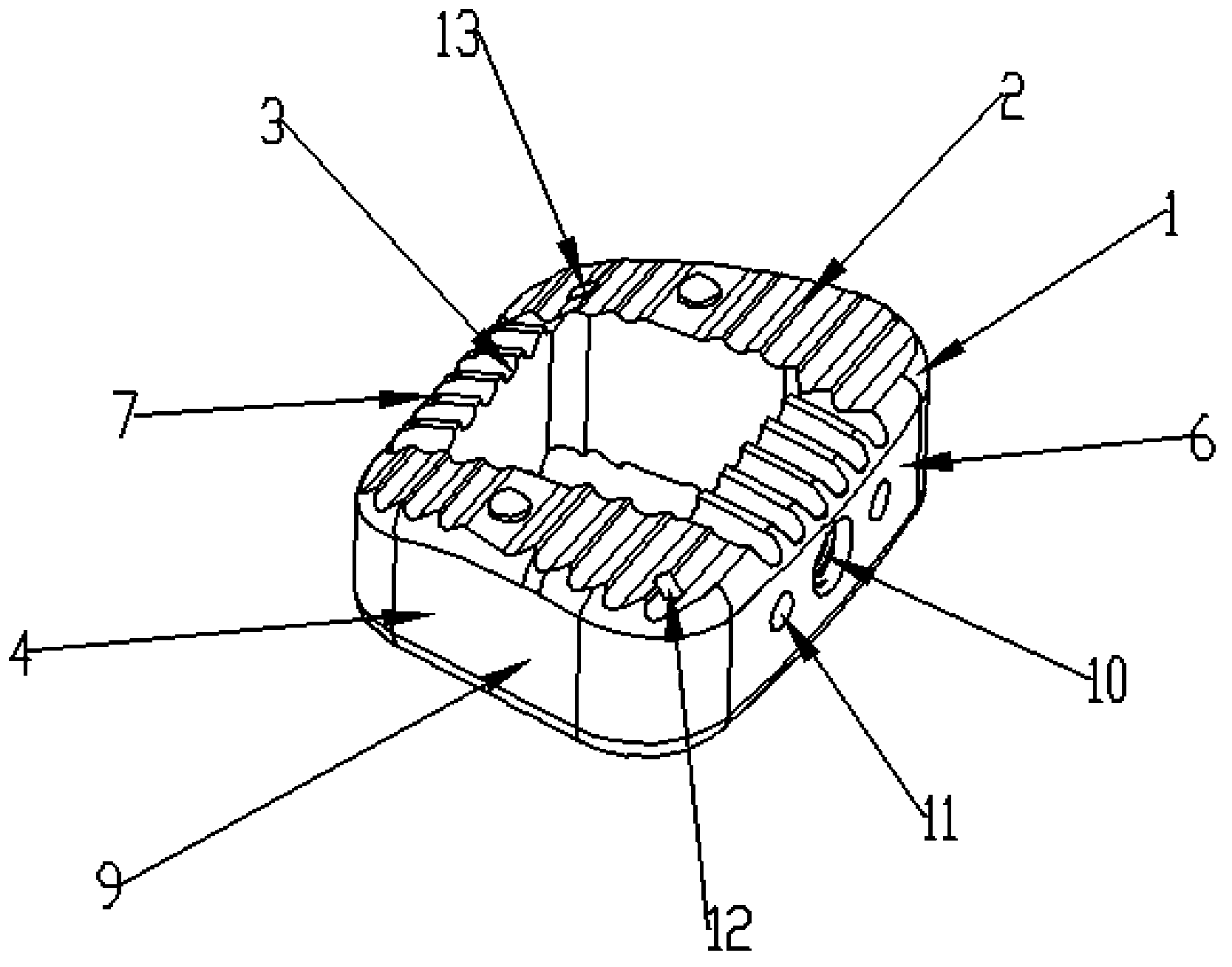
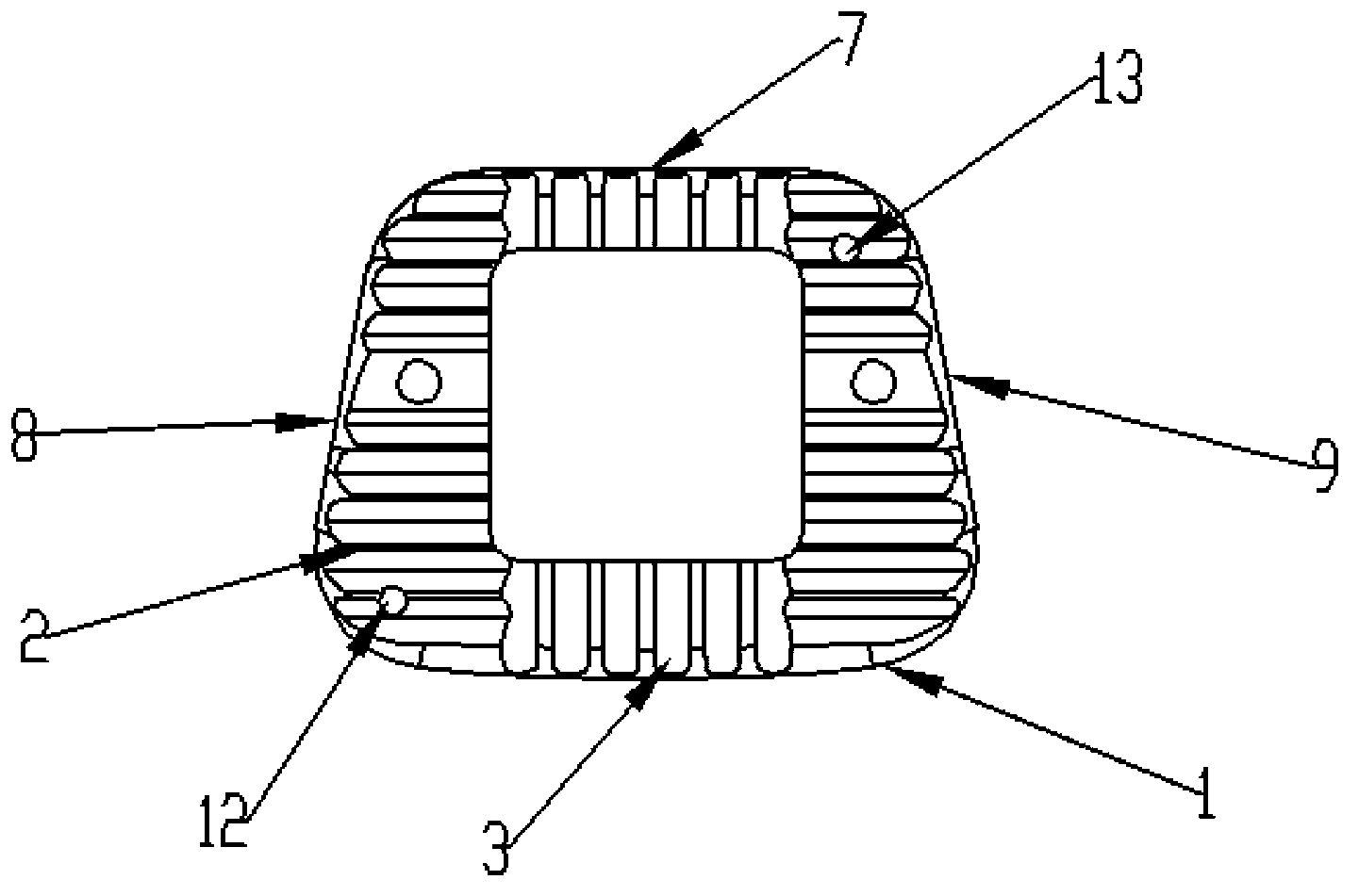
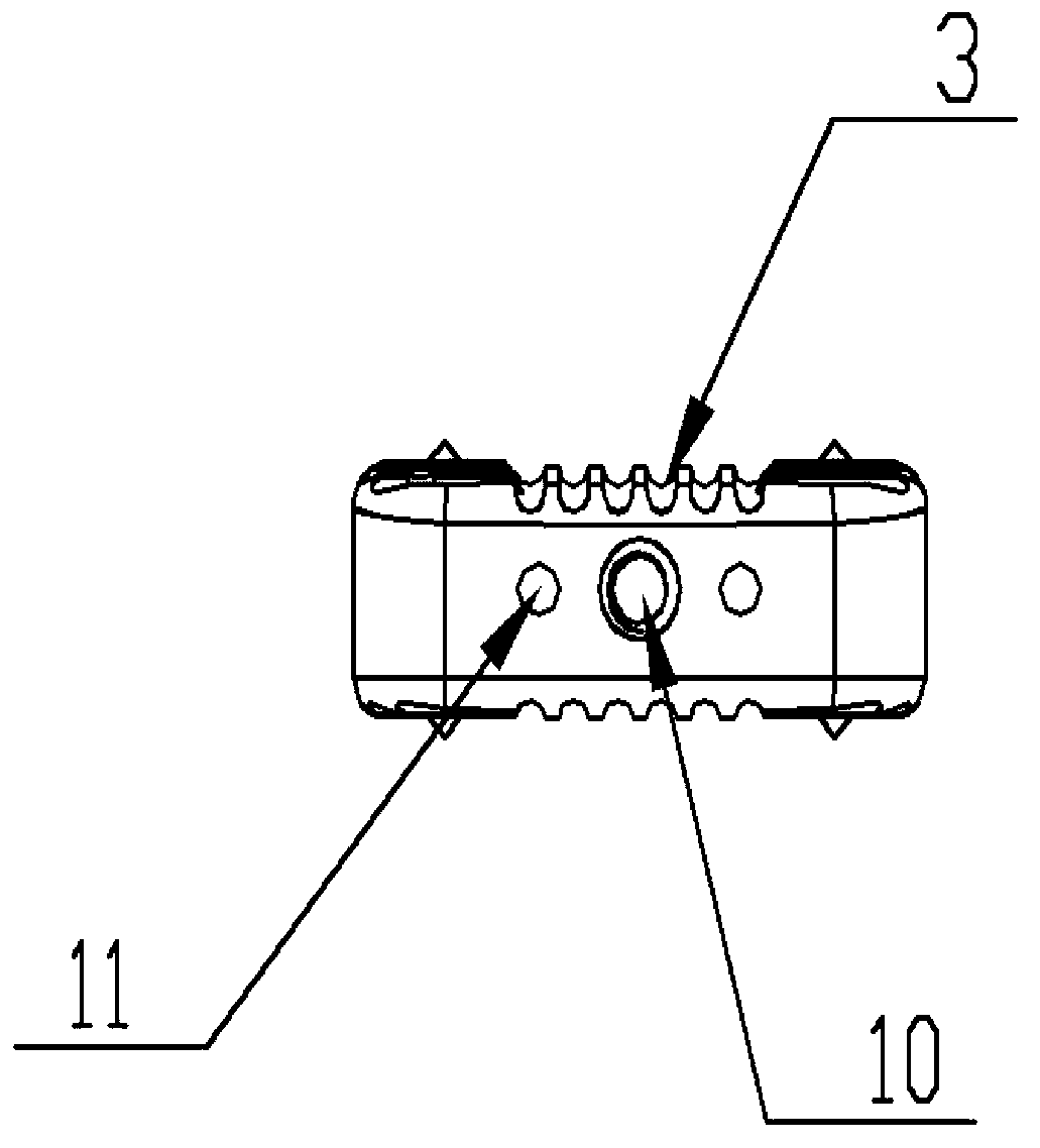
[0027] Such as Figure 1-4 As shown, the anterior cervical intervertebral fusion device provided by the present invention includes a main body 1 and a developing needle. The main body 1 is a hollow tetrahedron, the cross section of the tetrahedral outer periphery is trapezoidal, and the cross section of the hollow inner periphery is square or rectangular, including a front wall 6, a rear wall 7, a left side wall 9 and a right side wall 8, and the front wall 6 It is connected with the rear wall 7 through the left side wall 9 and the right side wall 8 . The four corners of the main body 1 are chamfered.

[0028] The left side wall 9 and the right side wall 8 are symmetrical structures, which are inwardly and backwardly inclined radially (starting from both ends of the front wall 6 and ending inwardly and backwardly radially at the rear wall 7), which is the difference between the trapezoidal cross section of the main body 1. Parallel opposite sides, the angle between both side...


PUM

PropertyMeasurementUnit
angleaaaaaaaaaa
thicknessaaaaaaaaaa
lengthaaaaaaaaaa

Abstract

The invention discloses an anterior cervical interbody fusion cage which comprises a main body and a development needle arranged on the main body, wherein the main body is a hollow tetrahedron; the cross section of the hollow periphery of the tetrahedron is ladder-shaped; the cross section of the hollow inner circumference of the tetrahedron is square or rectangular; the main body comprises a front wall, a rear wall, a left side wall and a right side wall; and the front wall is connected with the rear wall through the left side wall and the right side wall. The shape of the main body confirms to the anatomic form of the cervical intervertebral disc of a normal human body; while the safe implantation is ensured, the main body can be in tight contact with end plates of an upper cervical vertebral body and a lower cervical vertebral body under the compression state to create a good condition for bone fusion; and the cross section of the hollow inner circumference of the main body is square or rectangular, so that the contact surface of the main body and the end plates of the cervical vertebral bodies is increased to the greatest extent, the bone implementation amount is increased, and the fusion is speeded up.

Description

technical field [0001] The invention relates to a cervical intervertebral disc implant, in particular to an anterior cervical intervertebral fusion device designed according to the physiological characteristics and anatomical structure of the human cervical spine. Background technique [0002] Degenerative disc disease and trauma in the lower cervical spine often lead to disc herniation, causing limb pain and other neurological symptoms. The surgical treatment methods include anterior decompression, disc removal, intervertebral fusion, and fixation of the surgical segment. The gold standard needs to take three cortical bones from the patient's ilium, and then implant the cortical bone into the intervertebral space and fix it externally. However, in the follow-up process, there will often be serious defects of bone graft absorption, collapse, prolapse, loosening, displacement, protruding, or protruding into the spinal canal or intervertebral foramen, resulting in insufficient...

Claims


Application Information

Patent Timeline
Patent Type & Authority Applications(China)
IPC IPC(8): A61F2/44A61B17/70A61L27/18A61L27/06A61L27/50A61L31/06A61L31/02A61L31/18
CPCA61F2/44A61F2002/30001
Inventor 程顺巧尹泖谢坤张培发邹巍伟
Owner 广州聚生生物科技有限公司
Learn More