High-speed precision pneumatic micro main shaft

A kind of pneumatic micro and precise technology, applied in clamping, supporting, positioning device and other directions, can solve the problems of high cost and difficult to achieve

Active Publication Date: 2013-09-18
HUNAN UNIV
View PDF4 Cites 2 Cited by
  • Summary
  • Abstract
  • Description
  • Claims
  • Application Information

AI Technical Summary

Problems solved by technology

[0003] For the above-mentioned micro-spindle, if the manufacturing error and installation error of the micro-spindle are reduced by improving the machining accuracy of its parts, the precision and stiffness of the bearing are improved to reduce the run-out error of the micro-spindle when it rotates at an ultra-high speed, thereby improving the tool. Rotational accuracy, which can be very costly or even difficult to achieve

Method used


Image

  • High-speed precision pneumatic micro main shaft
  • High-speed precision pneumatic micro main shaft
  • High-speed precision pneumatic micro main shaft

Examples


Embodiment Construction

[0032] The present invention will be described in detail below in conjunction with the embodiments and accompanying drawings.

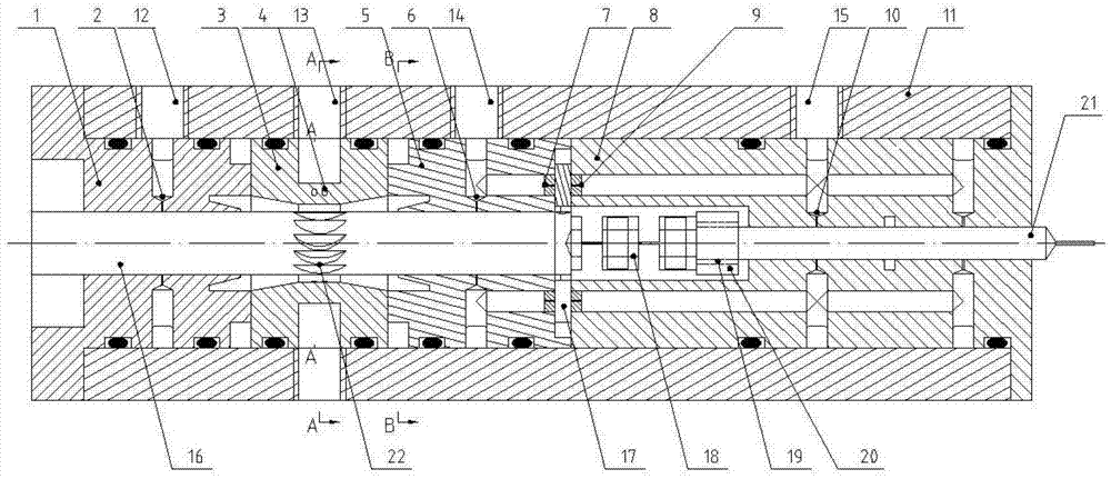
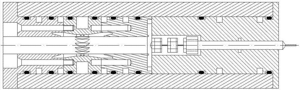
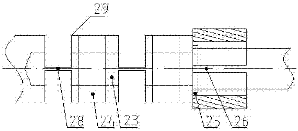
[0033] See attached figure 1 , figure 2 , image 3 , Figure 4 and Figure 5 , the turbine shaft 16 is installed in the casing 11 using the rear end bearing 1 and the intermediate bearing 5, the turbine shaft 16 is integrated with the turbine 22 and the outer diameter of the turbine 22 is not greater than the outer diameter of the turbine shaft 16, and the casing 11 is provided with Corresponding to the turbine 22, the jet-driven double-row nozzle 3 is provided with two circles of small holes 4, and the exhaust port 27 is arranged at both ends of the turbine chamber of the turbine 22. The actuator adopts the front end bearing 8 to be installed in the box body 11 The turbine shaft 16 is provided with a baffle 17 installed between the intermediate bearing 5 and the front end bearing 8, the rear end bearing 1 is provided with a first aerostatic radi...


PUM


Abstract

The invention discloses a high-speed precision pneumatic main shaft. In a turbine shaft (16), a back end bearing (1) and a middle bearing (5) are arranged in a box body (11); the turbine shaft (16) and a turbine (22) are integrated, and the outer diameter of the turbine (22) is not larger than the outer diameter of the turbine shaft (16); a nozzle driven by air current impact corresponding to the turbine (22) is arranged in the box body (11); air outlets (27) are formed at the two ends of the turbine chamber of the turbine (22); in an executing mechanism, a front end bearing (8) is arranged in the box body (11); the turbine shaft (16) is connected with the executing mechanism through an integral micro flexible connecting mechanism. The high-speed precision pneumatic micro main shaft has the advantages of novel and reasonable design, simple and compact structure, small size, simple manufacturing process, high rotating speed and small jumping errors, can be taken as a micro main shaft of a micro machine tool for performing fine cutting and fine grinding as well as a micro main shaft of other electromechanical or manual tool machines revolving at high speeds, ultrahigh speeds and high accuracies, and the like.

Description

technical field [0001] The invention relates to a spindle, in particular to a high-speed precision pneumatic micro-spindle. Background technique [0002] The miniaturization of parts and the high precision of size have put forward higher and higher requirements for its processing equipment. As a key component of micro-machine tools, micro-spindle directly determines the performance of micro-machine tools and the development and application of micro-cutting and micro-grinding technology. There are two main types of existing micro-spindles: one is the micro-spindle. Limited by heat dissipation conditions and rotation accuracy, its maximum speed is generally below 200,000 rpm, and some of them reach 300,000 rpm; the other is the micro-pneumatic turbine spindle. Such as various pneumatic turbine spindle products developed by NSK. The turbine-type micro-spindle driven and supported by airflow can reach a very high speed due to the small temperature rise of the airflow, low fri...

Claims


Application Information

Patent Timeline
IPC IPC(8): B23B19/02B23Q3/12
Inventor 周志雄李伟肖航宁铁军
Owner HUNAN UNIV
Why Eureka
Try Eureka