Spun yarn take-up apparatus

A pulling device and spinning technology, which is applied in the directions of transportation and packaging, textile and papermaking, and transportation of filamentous materials, etc., can solve problems such as troublesome and complicated initial threading operations, and achieve the effect of restraining large-scale growth.

Active Publication Date: 2013-09-18
TMT MACHINERY INC
View PDF11 Cites 9 Cited by
  • Summary
  • Abstract
  • Description
  • Claims
  • Application Information

AI Technical Summary

Problems solved by technology

This is not only cumbersome, but also because the workbench is common to a plurality of spinning draw-off devices, it is not possible to perform yarn spinning operations to mul

Method used


Image

  • Spun yarn take-up apparatus
  • Spun yarn take-up apparatus
  • Spun yarn take-up apparatus

Examples


Embodiment Construction

[0032] Preferred embodiments of the present invention will be described below.

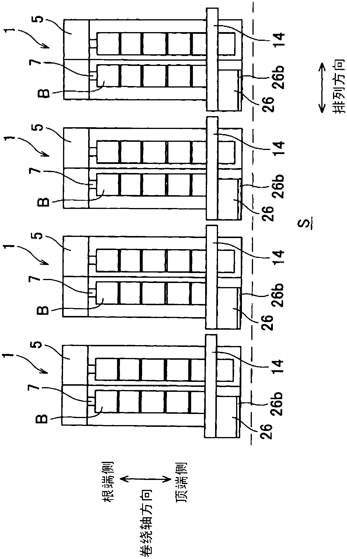
[0033] Such as figure 1 As shown, the spinning machine 1 (spinning machine) according to the present embodiment is considered to be, for example, the spinning machine 2 (see figure 2 ) for the arrangement of a plurality of spinnerets that spun a plurality of yarns Y or after loading and unloading a plurality of bobbins B from the top side of the bobbin base 7 that is supported by a cantilever described later, in order to be effective in a limited space A plurality of spinning drawing machines 1 are arranged in a plan view direction in an arrangement direction (horizontal and perpendicular to the axial direction of the bobbin base 7) ), and the top end side of the bobbin holder 7 becomes the work space S for the operator to perform work.

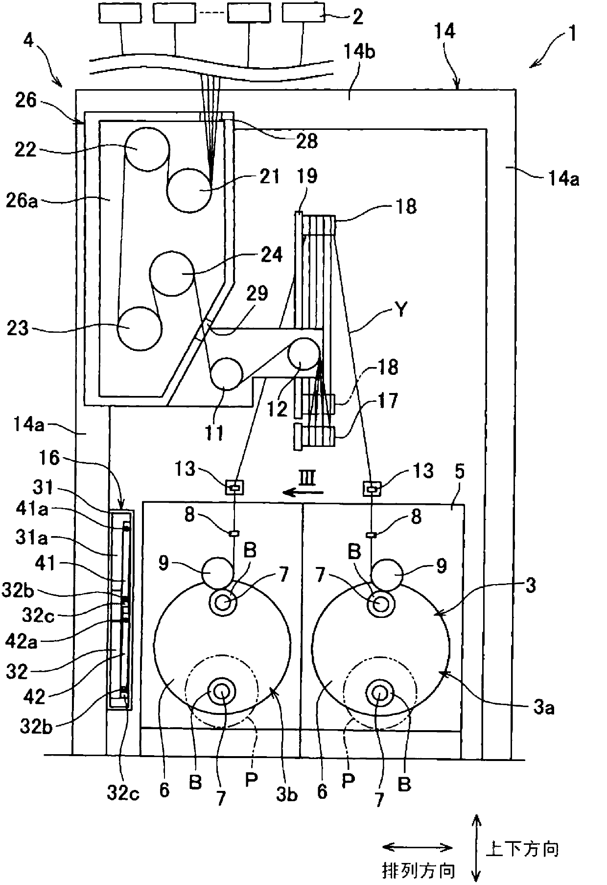
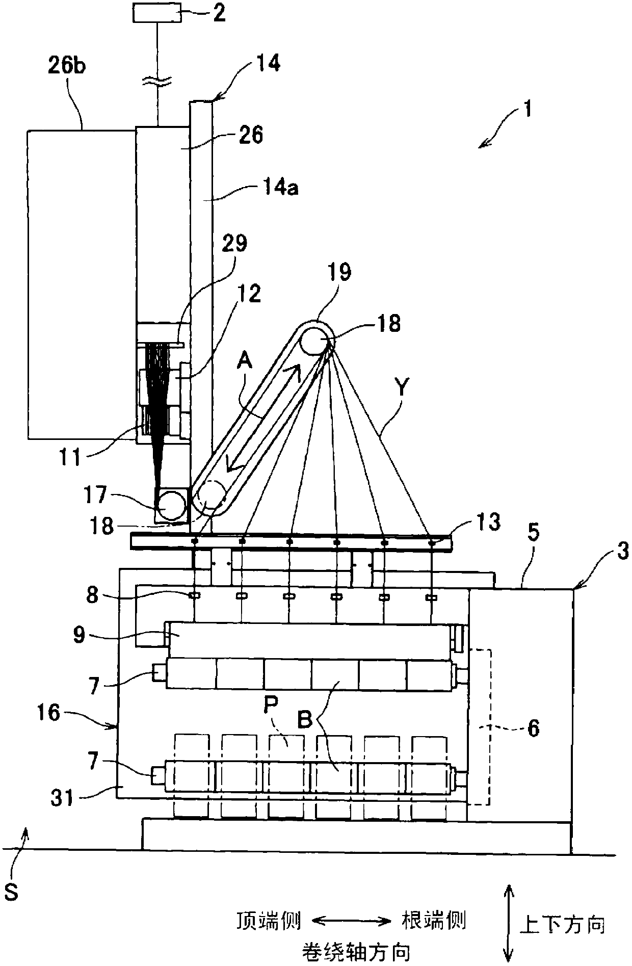
[0034] Each spinning traction machine 1 such as Figure 2 ~ Figure 6As shown, the plurality of yarns Y spun from the spinning machine 2 located above and sup...


PUM


Abstract

The present invention relates to a spun yarn take-up apparatus. In the case that the godet rollers are godet rollers, a working platform used for performing yam threading operation on the godet rollers does not obstruct the attachment and removal of bobbins on the bobbin holder and increases space efficiency. Onto godet rollers (21 to 24) arranged in parallel with a bobbin holder (7), a yam threading operation can be performed from the leading end side of the bobbin holder (7). A working platform (33) is able to selectively take any one of an operation posture in which footboards (41 and 42) extend in the horizontal direction and a retracted posture in which the footboards (41 and 42) extend in the vertical direction. In the operation posture, the working platform (33) is located on the leading end side of the bobbin holder (7). The retracted posture is deviated from a yarn winding device (3) with respect to an alignment direction. A storage (31) having a slidable component (32) stored therein is provided laterally to the yarn winding device (3). The working platform (33) is attached to the slidable component (32). Moving the slidable component (32) in the winding axis direction with the working platform (33) taking the retracted posture causes the working platform (33) to be stored into the storage (31).

Description

technical field [0001] The invention relates to a spinning take-up device comprising a yarn winding device for winding the yarn onto a bobbin. Background technique [0002] Patent Document 1 describes that a plurality of bobbins are arranged in a horizontal direction in a plane perpendicular to the axial direction of the bobbin holder to wind a thread onto a bobbin holder mounted on a bobbin holder capable of attaching and detaching the bobbin at the tip. In the case of the yarn winding device and the spinning take-up device composed of a godet roll and the like located upstream of the yarn winding device, it is made to be composed of two adjacent spinning take-up devices, and the corresponding side faces are separated from each other. A technique of arranging the groups of spinning-drawing devices facing each other with a small gap, and arranging such groups of spinning-drawing devices at intervals along the horizontal direction in a plane perpendicular to the axial directi...

Claims


Application Information

Patent Timeline
IPC IPC(8): D01D7/00
CPCB65H54/70B65H57/003B65H67/048B65H2701/3132D01D7/00D01D13/02
Inventor 石丸德希
Owner TMT MACHINERY INC
Why Eureka
Try Eureka