Eureka AIR delivers breakthrough ideas for toughest innovation challenges, trusted by R&D personnel around the world.

Air-injection vortex-spinning groove-shaped self-twist hollow spindle

A hollow spindle and groove type technology, applied in the textile field, can solve the problems of many details and low strength of air-jet vortex spinning yarns

Inactive Publication Date: 2013-09-18
DONGHUA UNIV
View PDF1 Cites 3 Cited by
  • Summary
  • Abstract
  • Description
  • Claims
  • Application Information

AI Technical Summary

Problems solved by technology

[0004] The technical problem to be solved by the present invention is to provide a grooved self-twisting hollow spindle for air-jet vortex spinning to solve the defects of many details and low strength in the air-jet vortex spinning yarn

Method used


Image

  • Air-injection vortex-spinning groove-shaped self-twist hollow spindle
  • Air-injection vortex-spinning groove-shaped self-twist hollow spindle
  • Air-injection vortex-spinning groove-shaped self-twist hollow spindle

Examples


Embodiment 1

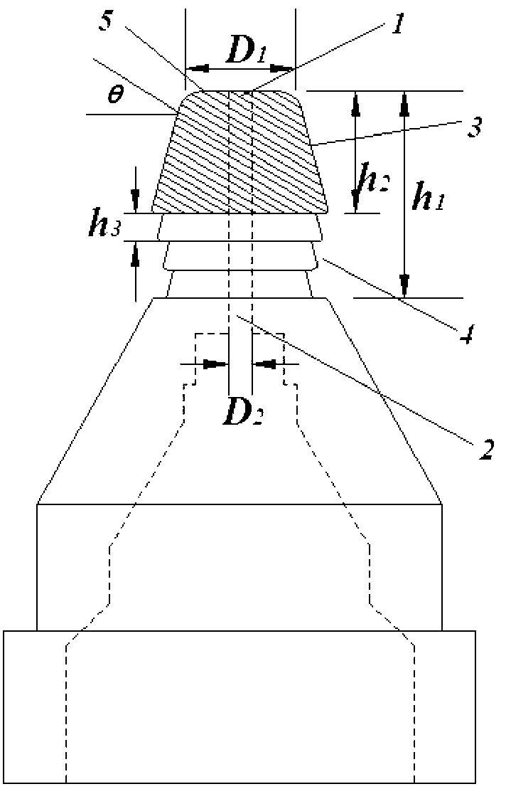
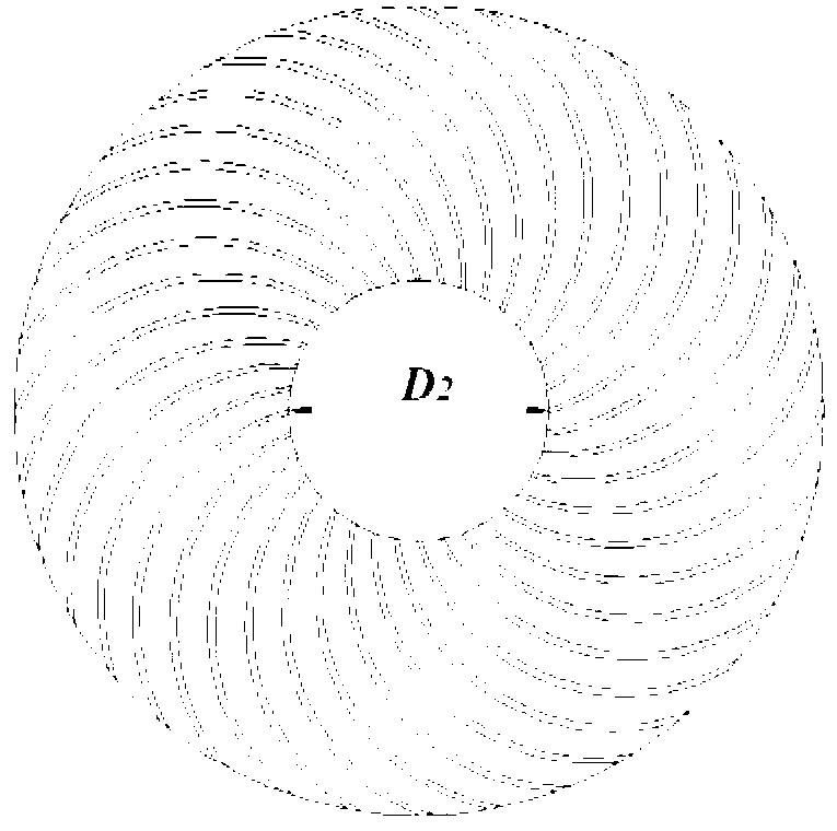
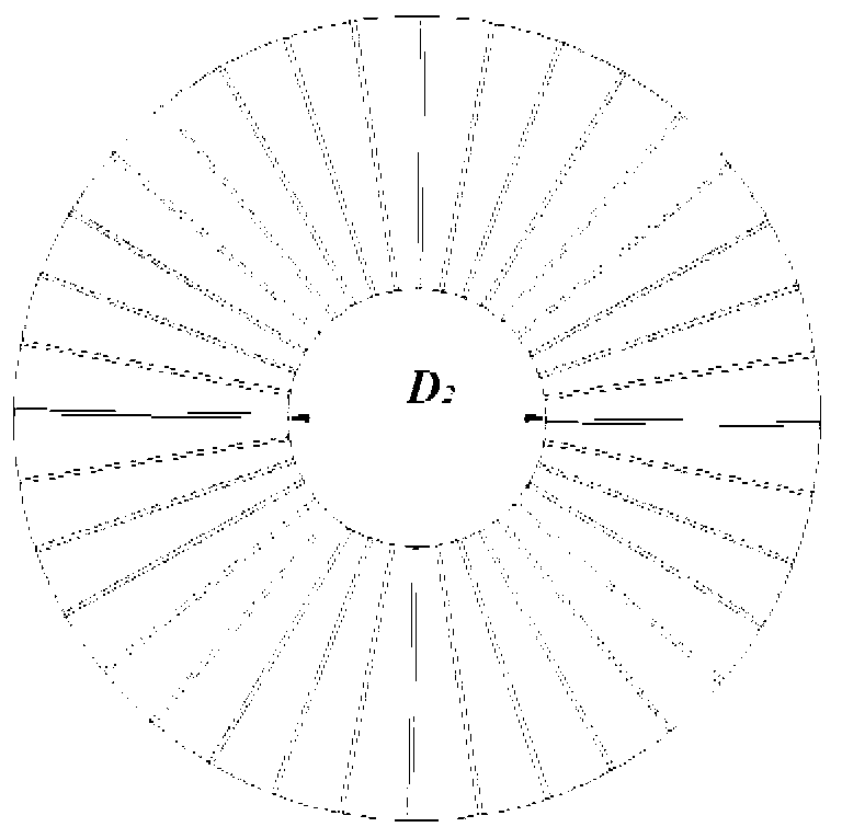
[0018] Such as Figure 1 ~ Figure 2 As shown, a grooved self-twisting hollow ingot for air-jet vortex spinning, including fiber inlet 1, yarn forming channel 2, wall spiral groove 3, circumferential stepped groove 4, cone top plane groove 5, diameter of hollow ingot cone top D. 1 , Yarn channel diameter D 2 , groove width D 3 , the height h from the top surface of the hollow ingot to the bottom surface of the circumferential groove 1 , The height h from the top surface of the hollow ingot to the top surface of the circumferential groove 2 , the height h of each step of the circumferential groove 3 , The spiral angle θ of the spiral groove on the wall surface, the main body of the hollow ingot. The number of steps of the circumferential stepped groove 4 is 3, the height of each step is 1.0mm, and the height from the top surface of the hollow ingot to the bottom surface of the circumferential groove is h 1 4.0mm; the cone-top plane groove 5 is 36, and the center of the yar...


PUM

PropertyMeasurementUnit
Heightaaaaaaaaaa
Diameteraaaaaaaaaa

Abstract

The invention relates to an air-injection vortex-spinning groove-shaped self-twist hollow spindle which comprises a fiber inlet (1), a yarn forming channel (2), a circumferential step groove (4), conical top plane arc grooves (5) and conical top wall face spiral grooves (3), wherein square groove bodies on a conical top plane of the hollow spindle are arc; included angles between the conical top wall face grooves and a horizontal direction are 20-40 degrees; the circumferential groove is step-shaped; and the quantity of steps is 1-3. According to the spindle, positive pressure bonded between a fiber at a free end and a wall face of the hollow spindle in a spinning process can be increased, and a friction force between the fiber and the wall face is increased, so that the twisting possibility of the fiber is improved, a cohesive force between the fibers in a yarn is increased, and the strength of the yarn is improved finally; in addition, the loss of the fibers can be reduced; and a use ratio of the fibers can be increased.

Description

technical field [0001] The invention belongs to the technical field of textiles, in particular to a grooved self-twisting hollow ingot for air-jet vortex spinning. Background technique [0002] Since the development of air-jet vortex spinning technology in 1995, it has quickly occupied the peak of spinning technology with its high-speed yarn forming speed and outstanding yarn properties. However, defects such as many details and low strength of air-jet vortex spinning yarn seriously restrict the popularization and application of its products. The main reasons are as follows: 1. In terms of processing method, the efficiency of eddy current twisting is greatly improved compared with mechanical twisting, but the high-pressure airflow is easy to pull out the fibers with insufficient control force of the yarn receiving body, resulting in the loss of fibers. loss, resulting in increased detail and insufficient strength in the final yarn. At the same time, the increase of tow rat...

Claims


Application Information

Patent Timeline
IPC IPC(8): D01H4/02
Inventor 张肖斌薛文良程隆棣
Owner DONGHUA UNIV
Why Eureka
Eureka Blog
Learn More