

Electronically controlled continuous adjustable dispensing device for barrier type water injection polywell
A polymer injection well and electronic control technology, which is applied in wellbore/well components, production fluid, earthwork drilling and production, etc. It can solve the problems of electrical appliances not working properly, inability to accurately inject cable seals, and inability to realize continuous adjustment of injection volume, etc. To achieve the effect of easy cable routing, improved precision and good sealing effect
- Summary
- Abstract
- Description
- Claims
- Application Information
AI Technical Summary
Problems solved by technology
Method used
Image

Examples
specific Embodiment approach 1
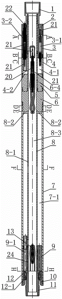
[0015] Specific implementation mode one: combine Figure 1-Figure 14 Describe this embodiment. The barrier-type water-through-water injection and polywell electronically controlled continuously adjustable dispensing device of this embodiment includes an upper joint 1, a lower joint 11, and a valve core 15. The valve core 15 is formed by rotating a plurality of identical busbars around the axis. The hollow rotary body, the device also includes an upper cable sleeve 2, a pin sleeve 3, a shell sleeve 4, a middle connecting sleeve 5, a connecting body 6, a working main cylinder 7, a central tube 8, a connecting sleeve 9, and a lower connecting sleeve 10 , water outlet sleeve 12, first cable joint 13, liquid outlet conduit 14, lead screw 16, first coupling 17, second cable joint 20, third cable joint 22, lower cable sleeve 24, outlet pressure sensor 25, circuit Plate 26, motor 27, second coupling 28, inlet pressure sensor 29, transmission shaft 30, water plug 31, connecting cylinde...
specific Embodiment approach 2
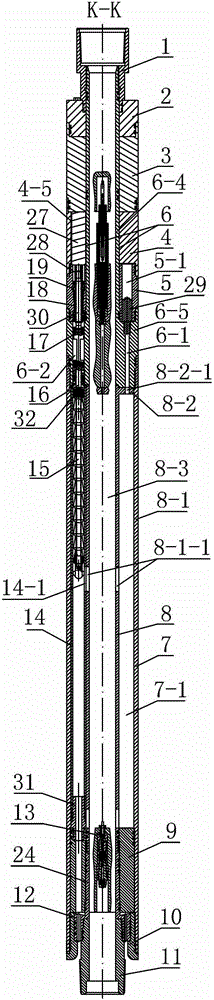
[0025] Specific implementation mode two: combination figure 2 This embodiment will be described. The first coupling 17 in this embodiment is a universal joint. With such arrangement, it has greater angular compensation capability, compact structure and high transmission efficiency. Others are the same as in the first embodiment.
specific Embodiment approach 3
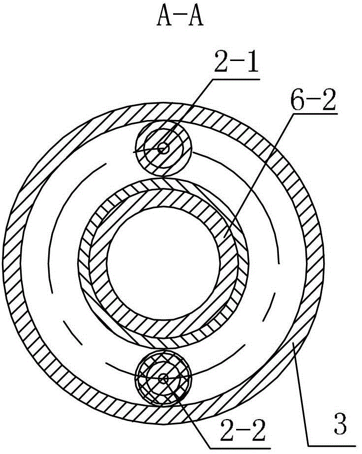
[0026] Specific implementation mode three: combination figure 1 , image 3 , Figure 4 , Figure 5 and Figure 6 Describe this embodiment, the first cable hole 2-1 and the second cable hole 2-2 are respectively arranged on the upper cable cover 2 of this embodiment along the axial direction of the working main cylinder 7, and the pin cover 3 is arranged along the axial direction of the working main cylinder. The cylinder 7 is provided with the upper third cable hole 3-1, the fourth cable hole 3-2 and the fifth cable hole 3-3 respectively in the axial direction. Six cable holes 4-1, the seventh cable hole 4-2 and the eighth cable hole 4-3, the column 6-5 is also provided with a ninth cable hole 6-3;
[0027] The first cable hole 2-1, the third cable hole 3-1 and the sixth cable hole 4-1 are coaxially arranged, the first cable hole 2-1, the third cable hole 3-1 and the sixth cable hole 4 -1 is pierced with at least three waterproof pins 21;
[0028] The second cable hole 2...
PUM
 Abstract
Description
Claims
Application Information