Electronic vacuum pump for brake vacuum booster of new energy vehicles

A technology for vacuum boosters and new energy vehicles, which is applied in the direction of pumps, machines/engines, mechanical equipment, etc. It can solve the problems that cannot meet the requirements of automobile brakes, vacuum pumps cannot meet the requirements of electric vehicle brakes, etc., to prevent stuck, High vacuum efficiency and reduced frictional resistance

Active Publication Date: 2015-12-30
常州市东南电器电机有限公司
View PDF8 Cites 9 Cited by
  • Summary
  • Abstract
  • Description
  • Claims
  • Application Information

AI Technical Summary

Problems solved by technology

[0005] The above-mentioned vacuum pump is used on gasoline vehicles, and the vacuum suction provided by the engine cannot meet the brakes of the car. Using the above-mentioned vacuum pump can only play an auxiliary vacuum role; when it is used on new energy electric vehicles, since the electric vehicle completely relies on the vacuum pump to provide vacuum, the above-mentioned The vacuum pump can not meet the requirements of electric vehicle brake work

Method used


Image

  • Electronic vacuum pump for brake vacuum booster of new energy vehicles
  • Electronic vacuum pump for brake vacuum booster of new energy vehicles
  • Electronic vacuum pump for brake vacuum booster of new energy vehicles

Examples


Embodiment 1)

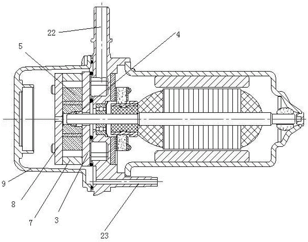
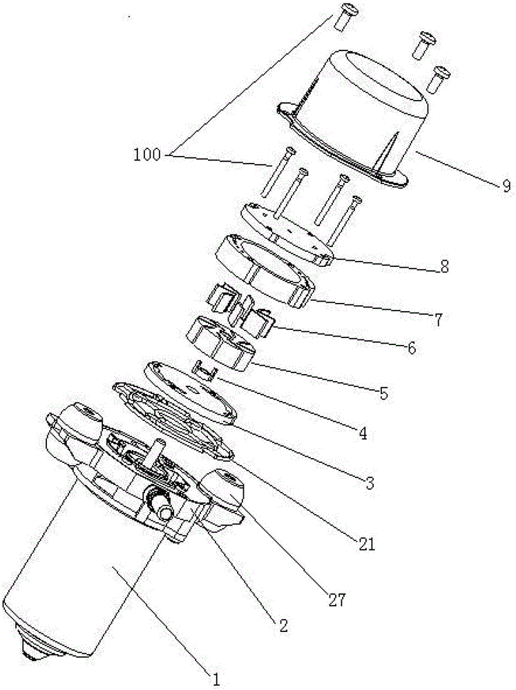
[0054] See figure 1 and figure 2 , the electronic vacuum pump for the new energy vehicle brake vacuum booster in this embodiment includes a motor assembly 1, a support base 2, a pump chamber lower cover 3, a drive sleeve 4, a pump rotor 5, blades 6, a pump chamber 7, and a pump chamber upper cover 8. Pump body cover 9 and fixing pin 100. The pump chamber lower cover 3 , the drive sleeve 4 , the pump rotor 5 , the vane 6 , the pump chamber 7 , the pump chamber upper cover 8 and the fixing pin 100 are arranged in the pump body cover 9 . The lower cover 3 of the pump chamber, the driving sleeve 4 and the pump rotor 5 are coaxially arranged with the output shaft of the motor assembly 1 .

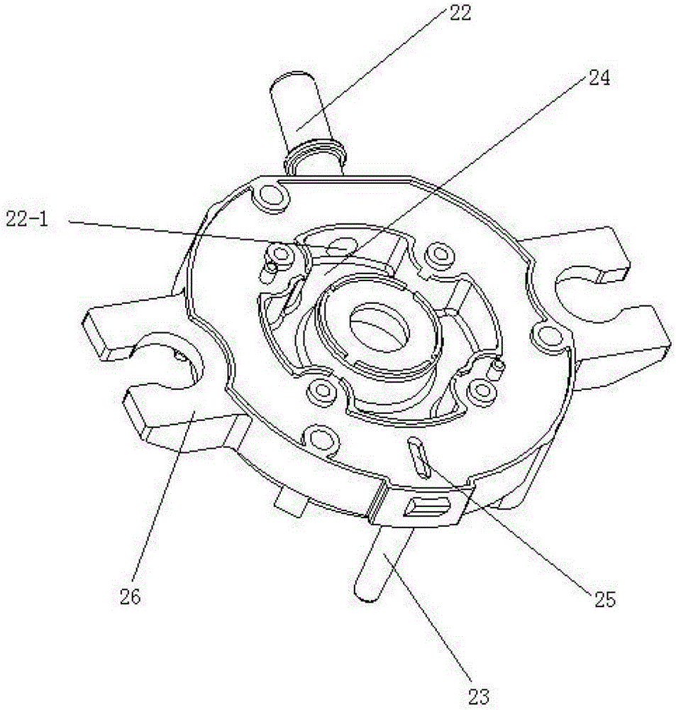
[0055] See image 3 , the support base 2 includes a sealing ring 21 , an air inlet pipe 22 , an air outlet pipe 23 , an air storage cavity 24 , an air outlet 25 , a mounting frame 26 and an installation sleeve 27 . The support base 2 is fixedly connected with the motor assembly 1 through th...


PUM


Abstract

The invention discloses an electronic vacuum pump for a new energy vehicle brake vacuum booster. The electronic vacuum pump comprises a motor assembly, a supporting base, a pump chamber lower cover, a driving sleeve, a pump rotor, blades, a pump chamber, a pump chamber upper cover, a pump body cover and fixing pins, wherein a left side air feeding slot of the pump chamber lower cover, a left side air feeding through hole of the pump chamber and a left side air feeding slot of the pump chamber upper cover are communicated with one another to form an air passageway; a right side air feeding slot of the pump chamber lower cover, a right side air feeding through hole of the pump chamber and a right side air feeding slot of the pump chamber upper cover are communicated with one another to form an air passageway; a flow guide slot of the pump chamber lower cover is communicated with an inner cavity of the pump chamber; an air discharging slot of the pump chamber upper cover is communicated with the inner cavity of the pump chamber; the flow guide slot of the pump chamber lower cover and the air discharging slot of the pump chamber upper cover are symmetric. When the vacuum pump works, an air path with four air inlets and two air outlets is formed; therefore, the air feeding resistance is greatly reduced, and the air feeding amount of the pump chamber is increased; under the equal energy consumption, the vacuumizing efficiency of the vacuum pump provided by the invention is higher.

Description

technical field [0001] The invention relates to a vacuum pump, in particular to an electronic vacuum pump for a new energy vehicle brake vacuum booster. Background technique [0002] There are two types of vacuum pumps used in domestic gasoline and diesel engine vehicles. One is mechanical vacuum pumps, which rely on engines to provide power. This type of vacuum pumps is currently produced by some domestic manufacturers and has gradually matured; the other is electronic vacuum pumps. Vacuum pumps rely on their own motors to provide power. At present, domestic automobile manufacturers basically import this type of vacuum pumps, especially imported German products; According to market feedback, there are no mature products, let alone domestic products that have achieved mass production and large-scale sales. [0003] As the country focuses on promoting the research and development of new energy vehicles and encourages the development of new energy vehicles, our company found ...

Claims


Application Information

Patent Timeline
Patent Type & Authority Patents(China)
IPC IPC(8): F04C25/02
Inventor 李余芝全亚伟
Owner 常州市东南电器电机有限公司
Why Eureka
Try Eureka