Non-symmetric involute worm and gear pair

An involute and asymmetric technology, applied in gear transmission, belt/chain/gear, portable lifting device, etc., can solve problems such as worm gear is easy to break

Active Publication Date: 2013-09-18
JIANGSU UNIV OF TECH
View PDF5 Cites 6 Cited by
  • Summary
  • Abstract
  • Description
  • Claims
  • Application Information

AI Technical Summary

Problems solved by technology

Under the existing technology, when the transmission has a larg...

Method used


Image

  • Non-symmetric involute worm and gear pair
  • Non-symmetric involute worm and gear pair
  • Non-symmetric involute worm and gear pair

Examples


Embodiment Construction

[0014] In order to make the content of the present invention more clearly understood, the present invention will be further described in detail below based on specific embodiments and in conjunction with the accompanying drawings.

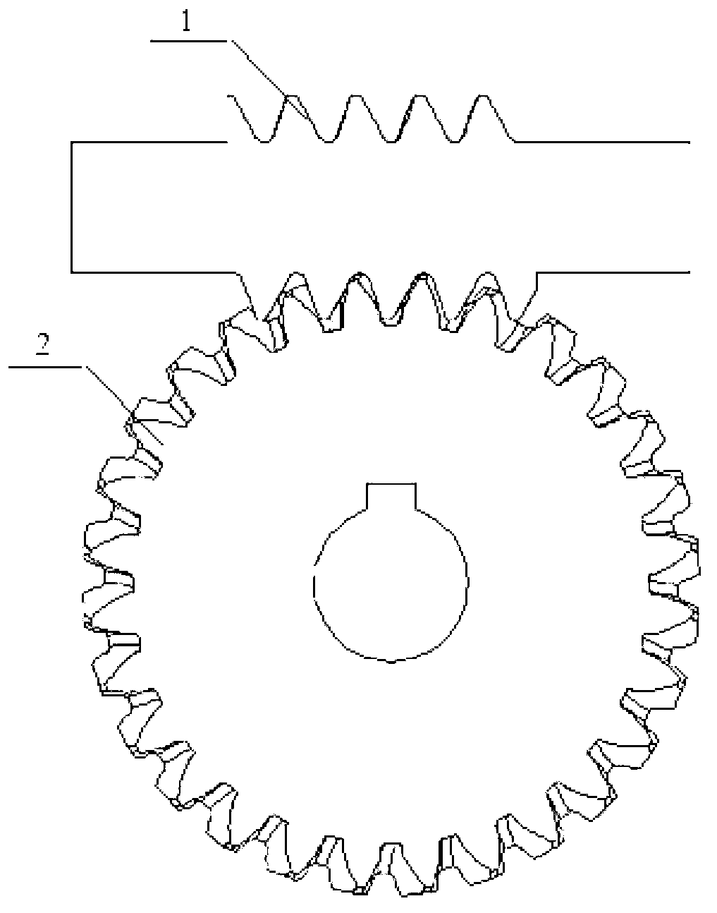
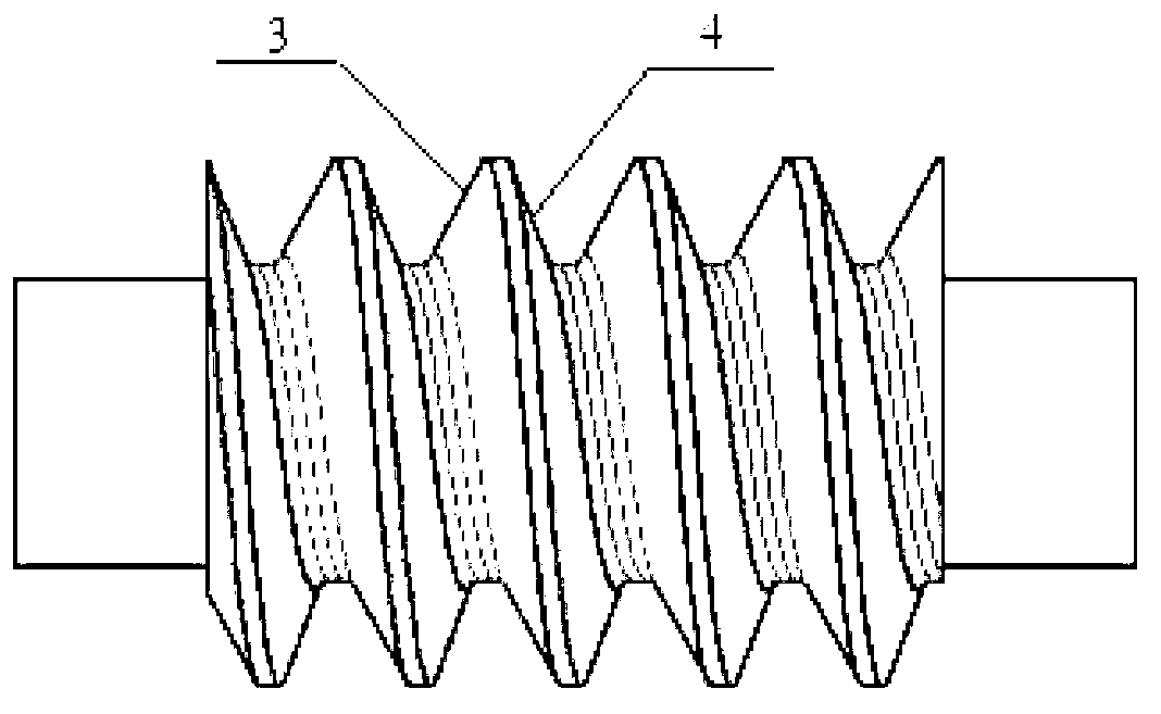
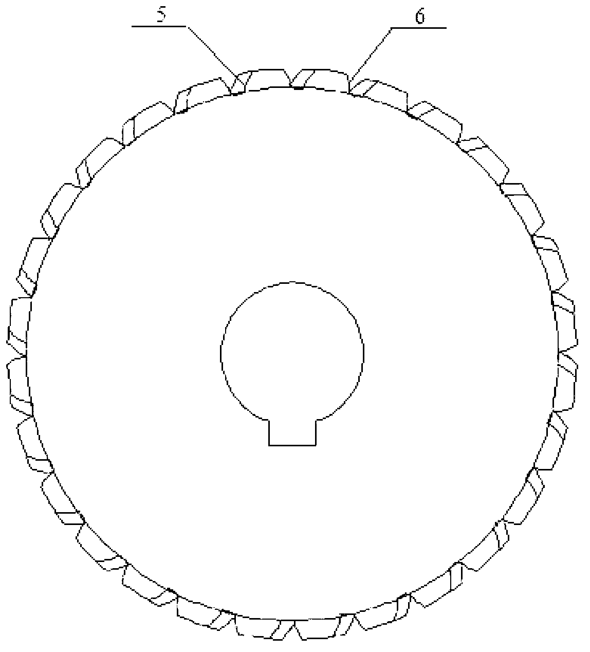
[0015] Such as Figure 1~4 As shown, an asymmetrical involute worm gear pair includes a worm 1 and a worm gear 2, the two sides of the teeth of the worm 1 have the worm meshing side tooth profile 3 and the worm non-meshing side tooth profile 4 respectively, and the gear teeth of the worm wheel 2 Both sides have the tooth profile 5 on the meshing side of the worm wheel and the tooth profile 6 on the non-engaging side of the worm wheel respectively, where the axial modulus of the worm 1 is m 1 , the end modulus of worm gear 2 is m 2 , the pressure angle of the tooth profile 3 on the meshing side of the worm is α 1 , the pressure angle of the tooth profile 4 on the non-meshing side of the worm is α 2 , the pressure angle of the tooth profile 5 on t...


PUM


Abstract

The invention discloses a non-symmetric involute worm and gear pair which comprises a worm rod and a worm wheel, wherein a worm rod engagement side tooth profile and a worm rod non-engagement side tooth profile are arranged on the two sides of a wheel tooth of the worm rod respectively; a worm wheel engagement side tooth profile and a worm wheel non-engagement side tooth profile are arranged on the two sides of a wheel tooth of the worm wheel respectively; the axial modulus of the worm rod is m1; the transverse modulus of the worm wheel is m2; the pressure angle of the worm rod engagement side tooth profile is alpha 1; the pressure angle of the worm rod non-engagement side tooth profile is alpha 2; the pressure angle of the worm wheel engagement side tooth profile is alpha 3; the pressure angle of the worm wheel non-engagement side tooth profile is alpha 4; to guarantee the worm rod and the worm wheel to be correctly engaged under the circumstance that the included angle sigma between the shafts of the worm rod and the worm wheel is 90 degrees, the addendum coefficients and the tip clearance coefficients of the worm rod engagement side tooth profile and the worm rod non-engagement side tooth profile meet the following conditions: a, alpha 1 is more than alpha 2 and alpha 3 is more than alpha 4; and b, when m1 is equal to m2, alpha 1 is equal to alpha 3 and alpha 2 is equal to alpha 4; and when m1 is not equal to m2, m1*cos alpha 1 is equal to m2*cos alpha 3 and m1*cos alpha 2 is equal to m2*cos alpha 4.

Description

technical field [0001] The invention relates to an asymmetric involute worm gear pair, which belongs to the technical field of worm gear mechanical transmission. Background technique [0002] At present, worm drive is widely used because of its advantages of large transmission ratio, stable transmission, small vibration and low noise. The performance and quality of worm gear transmission will ultimately affect the quality of machine products. Therefore, in order to meet the needs of modern mass production, it is required to continuously optimize the transmission performance of worm gears. In recent years, there have been great developments in the meshing theory of worm and worm gears, the calculation of bearing capacity, and new worm drives. In the process of worm gear transmission, the shape of gear teeth will not only affect the kinematic characteristics of worm gear transmission, but also affect the dynamic performance of worm gear transmission. In order to adapt to the...

Claims


Application Information

Patent Timeline
IPC IPC(8): F16H1/16F16H55/22F16H55/08
Inventor 李秀莲刘伟赵东升朱福先周金宇何庆王江涛
Owner JIANGSU UNIV OF TECH
Why Eureka
Try Eureka