

Bearing pressure-resistant member and process for making the same
a technology of pressure-resistant components and pressure-resistant components, which is applied in the direction of solid-state diffusion coatings, mechanical devices, coatings, etc., can solve the problems of difficult homogeneous dispersing of msub>, excessive long treatment time at the holding step, and deterioration of rolling fatigue strength, so as to improve significantly surface fatigue strength and reduce residual h2. , the effect of excellent surface fatigue strength
Inactive Publication Date: 2005-03-03
NISSAN MOTOR CO LTD
View PDF16 Cites 2 Cited by
- Summary
- Abstract
- Description
- Claims
- Application Information
AI Technical Summary
Benefits of technology
Further, residual H2 infiltrating into the metal of the element during the gas carburizing as described above, can be remarkably reduced by the subsequent tempering. However, if the residual H2 is insufficiently reduced, the element will suffer from delayed fracture or deterioration in bending fatigue strength and toughness. Recently, it has been recognized that rolling fatigue lives of rolling elements which undergo high bearing pressure upon coming into rolling contact with counterparts, will be considerably deteriorated due to the residual H2. Furthermore, since H2 is readily absorbed into the above-described carbide as well known, the residual H2 must be reduced in the gas carburizing treatment. In order to reduce the residual H2, there has been proposed baking in which an element is held at tempering temperature or less for several ten hours. This leads to decrease in production efficiency and increase in production cost. On the contrary, if the holding temperature is raised beyond a certain level, the element will be softened while the treatment time can be reduced.
An object of the present invention is to provide a bearing pressure-resistant member for use in power transmission, which has excellent surface fatigue strength with provision of M23C6 carbide homogeneously and finely dispersed in the matrix. Also, the object of the present invention is to provide a process for making the bearing pressure-resistant member by holding the element at a predetermined temperature to precipitate M23C6 carbide in the matrix in homogeneously and finely dispersed state, the process being capable of improving significantly surface fatigue strength. A further object of the present invention is to provide a bearing pressure-resistant member for use in power transmission, which is reduced in residual H2 even by gas carburizing or gas carbonitriding, and enhanced bending fatigue strength or rolling fatigue strength, and a process for making the bearing pressure-resistant member, capable of suppressing deterioration in bending fatigue strength or rolling fatigue strength which will be caused due to delayed fracture or hydrogen embrittlement.
Problems solved by technology
However, it is difficult to homogeneously disperse M23C6 carbide in the entire structure of the element or the outer surface layer thereof which has an increased C content by carburizing, only by the above-described isothermal heat treatment.
Further, at the quenching step following the above-described holding step, dense texture will not be obtained at the region having no carbide precipitated and dispersed, causing deterioration in rolling fatigue strength.
In European Patent Application Publication No. 1070760 A2 as discussed above, a region having no M23C6 carbide precipitated will be generated or an excessively long treatment time will be required at the holding step.
This causes increase in the production cost.
However, if the residual H2 is insufficiently reduced, the element will suffer from delayed fracture or deterioration in bending fatigue strength and toughness.
Recently, it has been recognized that rolling fatigue lives of rolling elements which undergo high bearing pressure upon coming into rolling contact with counterparts, will be considerably deteriorated due to the residual H2.
This leads to decrease in production efficiency and increase in production cost.
In U.S. Pat. No. 6,258,179 B1 as discussed above, coarse carbide tends to be produced at grain boundaries of austenite grains, so that rolling fatigue strength or bending fatigue strength will be deteriorated.
In addition, apparatus for use in the vacuum carburizing treatment is relatively expensive.
Method used
View moreImage
Smart ImageViewing Examples

Examples
examples
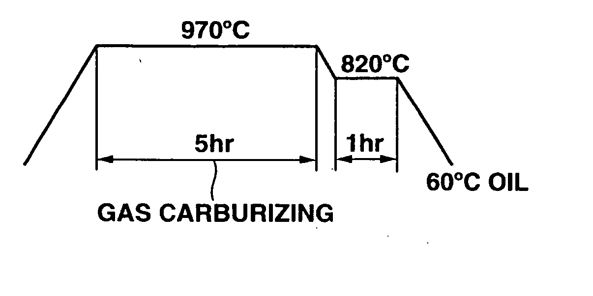
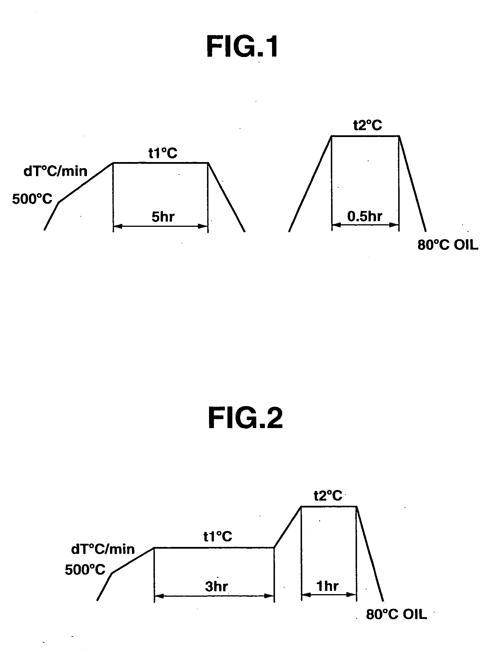
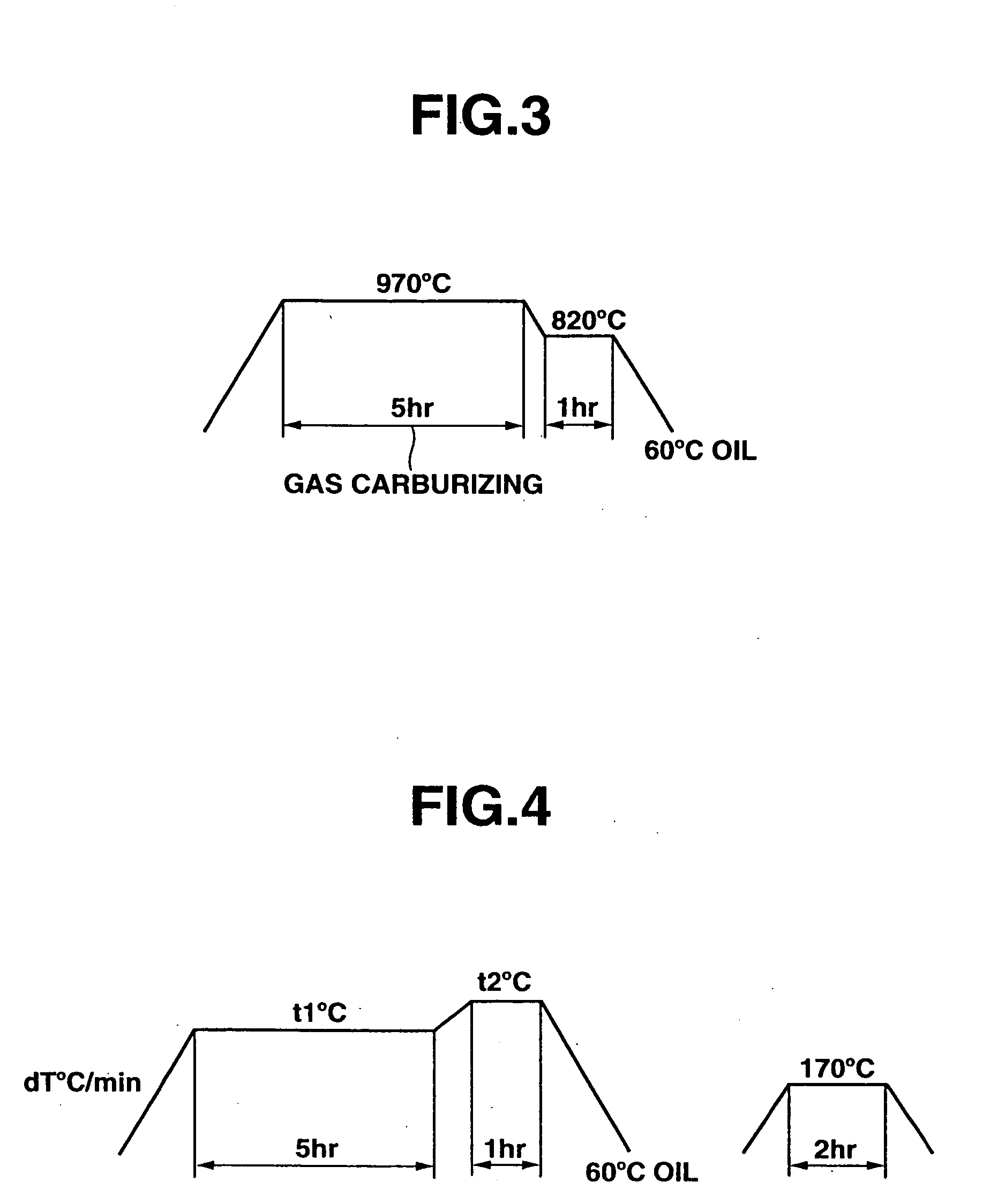
The present invention is described in more detail by way of examples and comparative examples by referring to the accompanying drawings. However, these examples are only illustrative and not intended to limit a scope of the present invention thereto.
Login to View More PUM
| Property | Measurement | Unit |
|---|---|---|
| temperature | aaaaa | aaaaa |
| temperature | aaaaa | aaaaa |
| temperature | aaaaa | aaaaa |
Abstract
A bearing pressure-resistant member, including a matrix and a carbide dispersed in the matrix, the carbide having an average particle size of not more than 0.3 μm. A carbon (C) content in an outer surface of the bearing pressure-resistant member is in a range of 0.6 to 1.5 mass percent. A process for making the bearing pressure-resistant member including subjecting a workpiece containing C to either of gas carburizing and gas carbonitriding to enhance the C content in the outer surface of the workpiece to 0.6 to 1.5 mass percent, holding the workpiece at a first temperature not more than an Ac1 transformation point under reduced pressure, heating the workpiece to a second temperature not less than the Ac1 transformation point under reduced pressure, followed by holding the workpiece at the second temperature, and subjecting the workpiece to quenching.
Description
BACKGROUND OF THE INVENTION The present invention relates to an element useable as a power transmission part such as gears and rolling-contact bearings, which necessitates a high surface fatigue strength. More specifically, this invention relates to a bearing pressure-resistant member suitable for use under a relatively high bearing pressure in a relatively high temperature range of about 100° C. to about 300° C., and relates to a process for making the bearing pressure-resistant member. There have been proposed methods for enhancing bearing pressure strength of the above-described power transmission part. Among the methods, there are hyper-eutectoid carburizing and high density carburizing. In these carburizing methods, M3C carbide such as Fe3C which is not readily decomposed in the above-described temperature range, is precipitated so that hardness of the part and resistance to tempering softening can be enhanced. European Patent Application Publication No. 1070760 A2 (correspon...
Claims
Login to View More Application Information
Patent Timeline
 Patent Type & AuthorityApplications(United States)
IPC IPC(8): C23C8/22C23C8/80F16C33/62
CPCC23C8/22F16C33/62C23C8/80
InventorKUREBAYASHI, YUTAKAKIMURA, TOSHIMITSUYAMAGUCHI, TAKUROOTANI, KEIZOUCHIYAMA, NORIKO
OwnerNISSAN MOTOR CO LTD