
Semi-finished product of high-frequency quenching component and its manufacturing method

一种高频淬火、制造方法的技术,应用在制造工具、提高能源效率、工艺效率的提高等方向,能够解决经济性下降、不能避免表层部的组织不均匀化等问题

Inactive Publication Date: 2018-03-30
NIPPON STEEL CORP
View PDF11 Cites 0 Cited by
  • Summary
  • Abstract
  • Description
  • Claims
  • Application Information

AI Technical Summary

Problems solved by technology

Although this method is effective for suppressing surface oxidation, phase change due to denitrification during induction quenching (ε transformation to austenite during heating, and then transformation to martensite and retained austenite by quenching) is impossible. Unavoidable, unavoidable inhomogeneity of superficial tissue
In addition, when the atmosphere is controlled in the induction hardening, there is a concern that the economic efficiency will be reduced due to the reduction of the work efficiency.

Method used

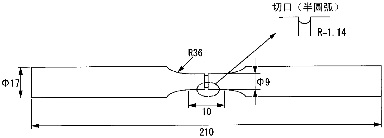
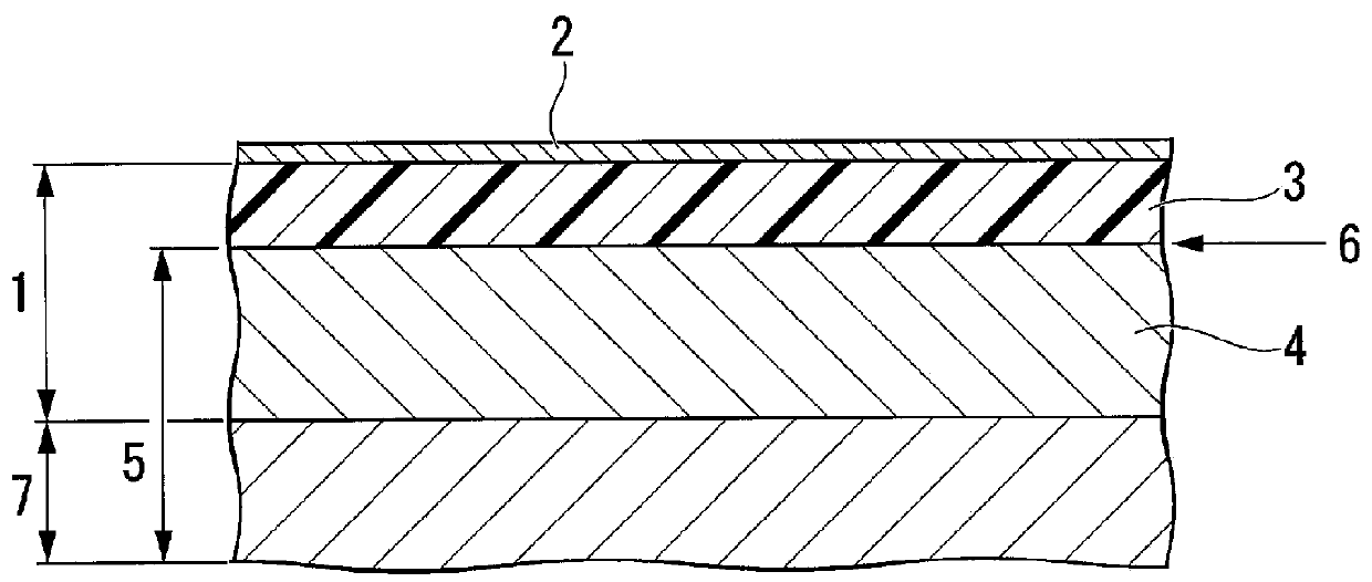

Image

  • Semi-finished product of high-frequency quenching component and its manufacturing method
  • Semi-finished product of high-frequency quenching component and its manufacturing method
  • Semi-finished product of high-frequency quenching component and its manufacturing method

Examples


Embodiment

[0127] Hereinafter, the present invention will be specifically described by way of examples. The conditions in the examples are one example of conditions employed to confirm the feasibility and effects of the present invention, and the present invention is not limited to this one example of conditions. In the present invention, various conditions can be adopted within a range in which the object of the present invention can be achieved without departing from the gist of the present invention.


PUM


Abstract

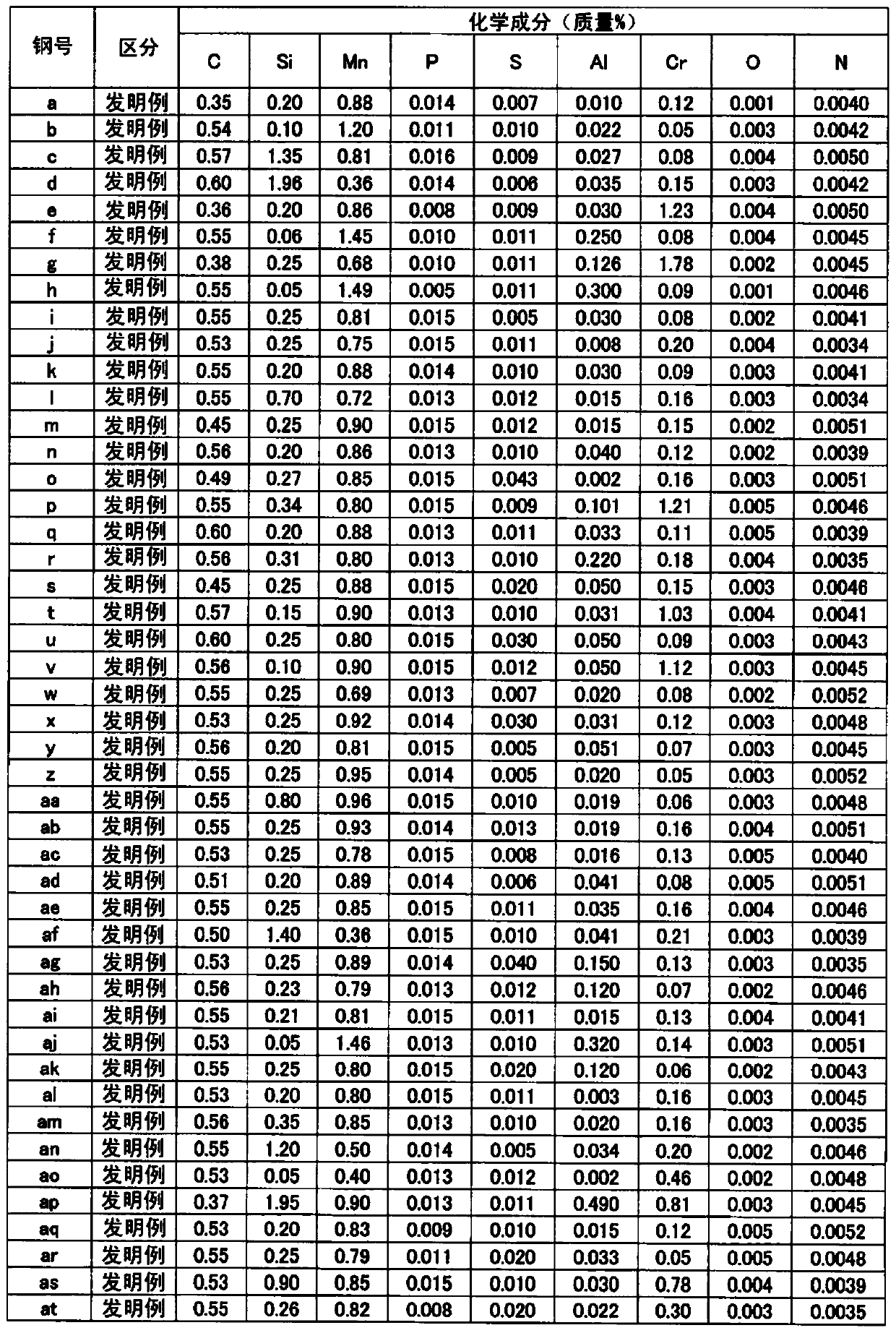
A Roughly shaped material for induction hardened components including: a steel as a base metal including, as a chemical composition, by mass%, C: 0.35% to 0.6%, Si: 0.02% to 2.0%, Mn: 0.35% to 1.5%, Al: 0.001% to 0.5%, Cr: 0.05% to 2.0%, S: 0.0001% to 0.05%, N: 0.003% to 0.0120%, P: 0.03% or less, O: 0.0050% or less, an iron nitride layer having a thickness of 0.1 µm to 50 µm in a depth direction is formed at a surface, and a volume fraction of a ³' phase, which is a Fe nitride, in the iron nitride layer, is 80% or more.

Description

technical field [0001] The present invention relates to an induction hardened component, a semi-finished product thereof, and a method for producing the induction hardened member. In particular, it relates to components with high surface fatigue strength suitable for power transmission components such as automobiles, such as semi-finished products of induction hardened components such as gears, continuously variable transmissions, constant velocity joints, hubs, and bearings, and their manufacturing methods. [0002] This application claims priority based on Japanese Patent Application No. 2013-047013 for which it applied to Japan on March 8, 2013, and uses the content here. Background technique [0003] High surface fatigue strength is required for power transmission members such as gears of an automatic transmission, pulleys of a continuously variable transmission, constant velocity joints, and hubs. Conventionally, surface carburized steels such as JISSCr420 and SCM420 w...

Claims


Application Information

Patent Timeline
Patent Type & Authority Patents(China)
IPC IPC(8): C23C8/26C21D1/06C21D9/32C21D9/40C22C38/00C22C38/60C23C8/18C23C8/34C23C8/80
CPCC21D1/06C21D1/10C21D1/74C21D9/00C21D9/32C21D9/40C22C38/001C22C38/002C22C38/008C22C38/02C22C38/04C22C38/06C22C38/22C22C38/24C22C38/26C22C38/28C22C38/32C22C38/34C22C38/42C22C38/44C22C38/46C22C38/48C22C38/50C22C38/60C23C8/18C23C8/26C23C8/34C23C8/80Y02P10/25
Inventor 吉田卓小山达也
Owner NIPPON STEEL CORP
Learn More