
Backflow hydraulic mechanical automatic variable speed transmission device

An automatic speed change and transmission technology, applied in the direction of fluid transmission, transmission, mechanical equipment, etc., can solve the problems of low efficiency, development restrictions, and low transmission efficiency.

Inactive Publication Date: 2015-11-25
CHONGQING ZHIHUAN TRANSMISSION TECH DEV CO LTD
View PDF8 Cites 0 Cited by
  • Summary
  • Abstract
  • Description
  • Claims
  • Application Information

AI Technical Summary

Problems solved by technology

AMT is an important development direction of automatic transmission technology, but due to the restriction of fuel economy and emission regulations, the development of AMT is limited to a certain extent
3. Mechanical continuously variable transmission (CVT.ContinuouslyVariableTransmission), which overcomes the shortcomings of discontinuous gear ratio and excessive number of parts inherent in the first two automatic transmissions, but because CVT is a friction transmission, it leads to low efficiency, so The transmission belts or chains used are difficult to manufacture, require high processing precision, use higher material requirements, and are even more difficult to maintain.
4. Dual-clutch automatic transmission (DCT.Double Clutch Transmission), the clutch uses two clutches, the two clutches are respectively connected to the two input shafts, its main feature is that the power of the engine is constantly changing during the gear shifting process. It is transmitted to the wheels. This shifting process is power shifting. The vehicle realizes power shifting, which greatly improves the comfort of shifting, but there are also shortcomings such as low transmission efficiency.

Method used


Image

  • Backflow hydraulic mechanical automatic variable speed transmission device
  • Backflow hydraulic mechanical automatic variable speed transmission device

Examples


Embodiment Construction

[0025] Below in conjunction with accompanying drawing and embodiment the present invention will be further described:

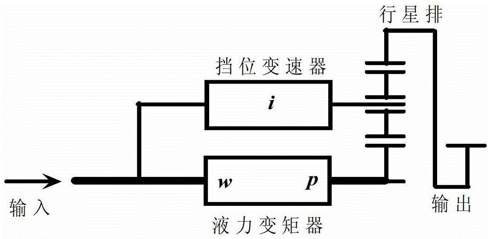
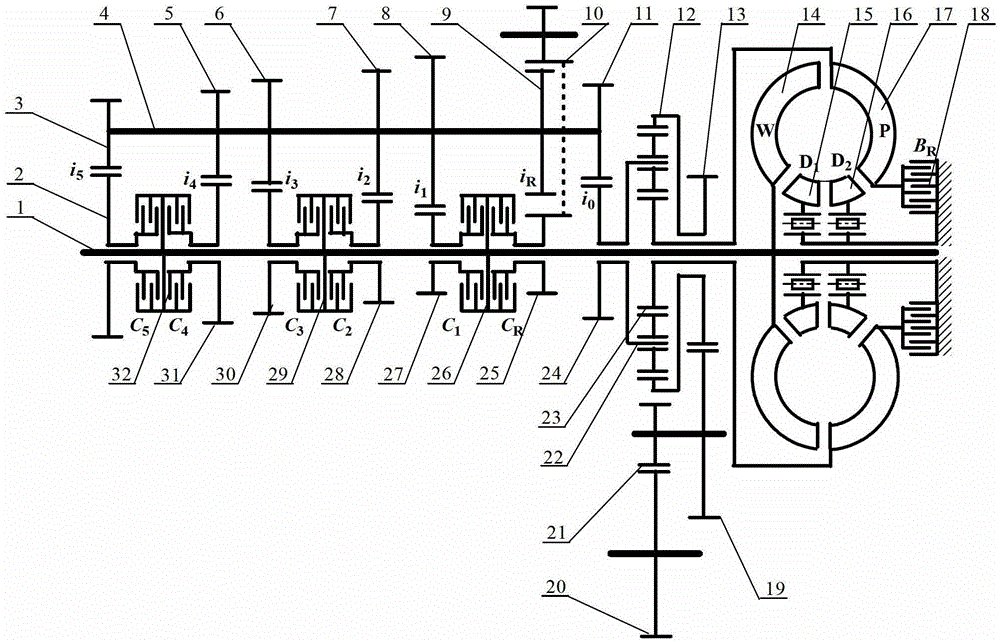
[0026] Such as figure 1 and figure 2 Shown: a return type hydromechanical automatic variable speed transmission, including an input shaft 1, an intermediate shaft 4, a planetary row and a hydraulic torque converter, wherein the planetary row includes a planetary carrier 22, a sun gear 23 and a ring gear 12 , the hydraulic torque converter includes a pump wheel 17 and a turbine wheel 14, one end of the intermediate shaft 4 is connected to the input shaft 1, the other end is connected to the planet carrier 22, and the sun gear 23 is connected to the pump wheel 17 connected, the turbine 14 is fixedly connected with the input shaft 1, the input shaft 1 and the intermediate shaft 4 are arranged in parallel, wherein the input shaft 1 is provided with a transition driven gear 24, and the intermediate shaft 4 is fixedly sleeved with The transition driving gear 11,...


PUM


Abstract

The invention discloses a reverse-flow type hydrodynamic mechanical automatic variable transmission device. The variable transmission device comprises an input shaft, an intermediate shaft, a planetary line and a hydraulic torque converter, wherein the planetary line comprises a planet carrier, a sun gear and a gear ring; the hydraulic torque converter comprises a pump impeller and a turbine; one end of the intermediate shaft is connected with the input shaft, and the other end is connected with the planet carrier; the sun gear is connected with the pump impeller; the turbine is fixedly connected with the input shaft. The inherent shunting / converging power and rate combination property of the planetary line is utilized to reversely arrange the hydraulic torque converter in a reflow path to greatly lower power loss, the continuous speed adjustment function of the hydraulic torque converter is utilized to realize the whole-course stepless change of the whole variable-speed system, and the power reflow property is utilized to continually retain the low-speed torque boosting effect of the whole variable transmission system, so that the purposes of high transmission efficiency, low power loss and the like are achieved.

Description

technical field [0001] The invention belongs to the technical field of mechanical transmission, and in particular relates to a backflow type hydraulic mechanical automatic variable speed transmission device. Background technique [0002] At present, the continuously variable transmission devices widely used in automobiles mainly include metal belt / metal chain transmission and hydromechanical variable speed transmission. For an ideal car continuous variable speed system, its gear ratio range is above 6 to ensure that the steady-state operating point of the engine is always on the optimal and economical line under different throttle openings. As for the metal belt / metal chain continuously variable transmission device, due to the limitation of the structure size, the variation range of the speed ratio is usually about 5.1, which is lower than the theoretical speed ratio variation range of the car transmission system. On the premise of satisfying the dynamic performance of the ...

Claims


Application Information

Patent Timeline
Patent Type & Authority Patents(China)
IPC IPC(8): F16H47/08
Inventor 孙冬野王勇刘升杨勇
Owner CHONGQING ZHIHUAN TRANSMISSION TECH DEV CO LTD
Learn More