
Mechanism for tooth clearance adjustment and linear actuation

A linear actuator, backlash technology, applied to components with teeth, mechanical equipment, belts/chains/gears, etc., can solve expensive and other problems

Active Publication Date: 2013-09-18
TRUMPF WERKZEUGMASCHINEN GMBH & CO KG
View PDF5 Cites 1 Cited by
  • Summary
  • Abstract
  • Description
  • Claims
  • Application Information

AI Technical Summary

Problems solved by technology

[0004] In order to achieve the adjustment of backlash and tooth tip clearance with high precision, existing measures require very high-quality and space-consuming actuators and control system designs, which are very expensive

Method used


Image

  • Mechanism for tooth clearance adjustment and linear actuation
  • Mechanism for tooth clearance adjustment and linear actuation
  • Mechanism for tooth clearance adjustment and linear actuation

Examples


Embodiment Construction

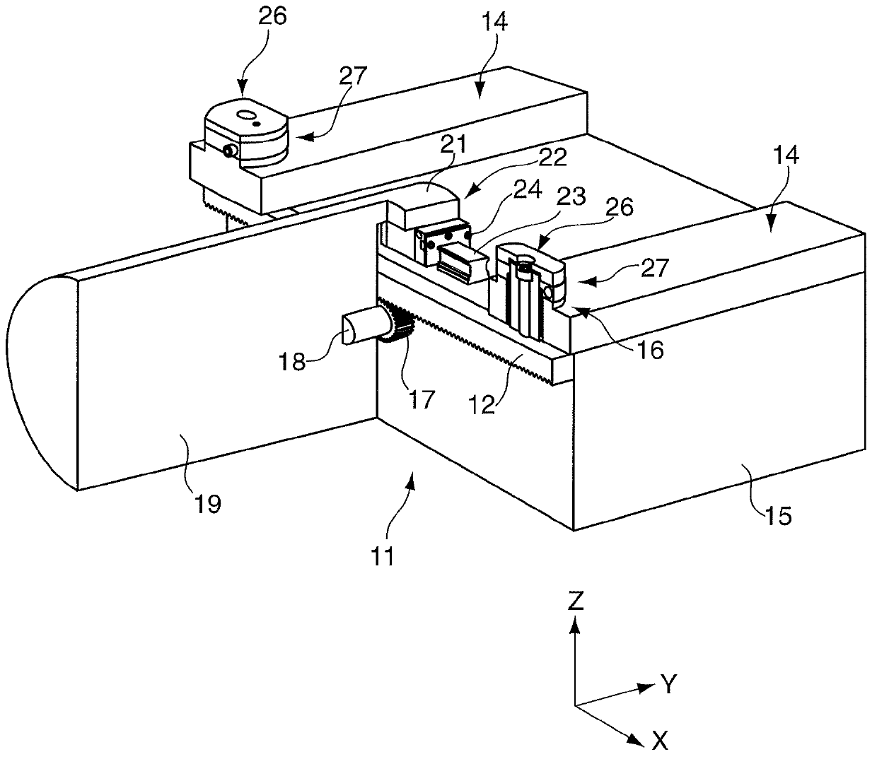
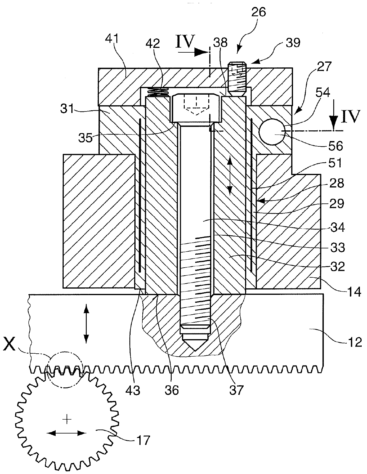
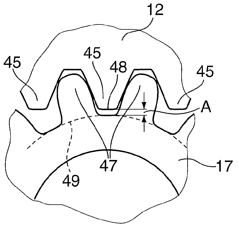
[0028] exist figure 1 A perspective view of a linear actuator 11 with a mechanism 10 for backlash adjustment is shown in . The mechanism 10 for backlash adjustment comprises a holding element 21 on which the gear wheel 17 is mounted. This gear 17 is in contact with the rack 12 or an additional gear contained or mounted via the carrier element 14 . In order to adjust the backlash A between the gear 17 and the rack 12 or between the gear 17 and an additional gear, a backlash adjusting device 26 with a fastening device 27 is provided, wherein said fastening device is Figures 2 to 4 in more detail.

[0029] in accordance with figure 1 In an embodiment of the present invention, the toothed rack 12 is connected to a carrier element 14 which in turn is detachably connected to a base (base body) 15 . The carrier element 14 can also be provided in one piece with the base 15 . The base 15 is, for example, part of a machine tool or processing machine, in particular a laser processi...


PUM


Abstract

The invention provides a The mechanism for gear clearance adjustment comprises: a retaining element, on which a first gear wheel is mounted; a carrier element, on which a gear rack or a second gear wheel is mounted; at least one clearance adjustment device positioned on the carrier element or on the retaining element by a clamping device and changeable between an unloaded state for the adjustment of a gap in a radial direction between the first gear wheel and the gear rack or between the first gear wheel and the second gear wheel and a loaded state after the adjustment of the gap so as to secure the adjusted gap, wherein the clamping device comprises a clamping bush which contains a pillar guide which is connected directly or indirectly to the gear wheel, the gear rack or the second gear wheel, whereby the pillar guide is moveable axially within the clamping bush when the clamping bush is in an unloaded state.

Description

technical field [0001] The invention relates to a mechanism for backlash adjustment and a linear actuator comprising a holding element on which a gear is mounted and a carrier element on which a rack or an additional gear is mounted. Background technique [0002] In a gear or rack and pinion drive, the tooth mesh and addendum clearance must be set to allow precise adjustment movements. If the tip clearance is too large, the traversing paths may be adjusted incorrectly, so that for example machining operations on workpieces arranged on the traversable carriage may be performed imprecisely. If the tip clearance is too small, wear between the rack and the pinion increases. [0003] A linear drive such as a rack and pinion drive is known from patent publication DE 10 2004 448 A1, in which the tooth tip clearance between the pinion and the rack can be adjusted by means of an actuator. Such actuators are known, for example, as piezoelectric actuators, shape memory actuators or e...

Claims


Application Information

Patent Timeline
IPC IPC(8): F16H55/28F16H55/18
CPCF16H55/28Y10T74/18808Y10T74/19623
Inventor T·梅克
Owner TRUMPF WERKZEUGMASCHINEN GMBH & CO KG
Learn More