
Logical channel grouping method in LTE system

A technology of logical channel groups and logical channels, applied in transmission systems, digital transmission systems, wireless communications, etc., can solve the problems of waste of resources, waste of system air interface resources, and large differences in bit rate requirements, and achieves reduction of resource allocation errors and savings. Air interface resources, the effect of reducing the frequency of use

Inactive Publication Date: 2013-09-18
POTEVIO INFORMATION TECH
View PDF2 Cites 40 Cited by
  • Summary
  • Abstract
  • Description
  • Claims
  • Application Information

AI Technical Summary

Problems solved by technology

[0009] First: Unnecessary reporting of multiple logical channel groups will bring overhead of air interface resources
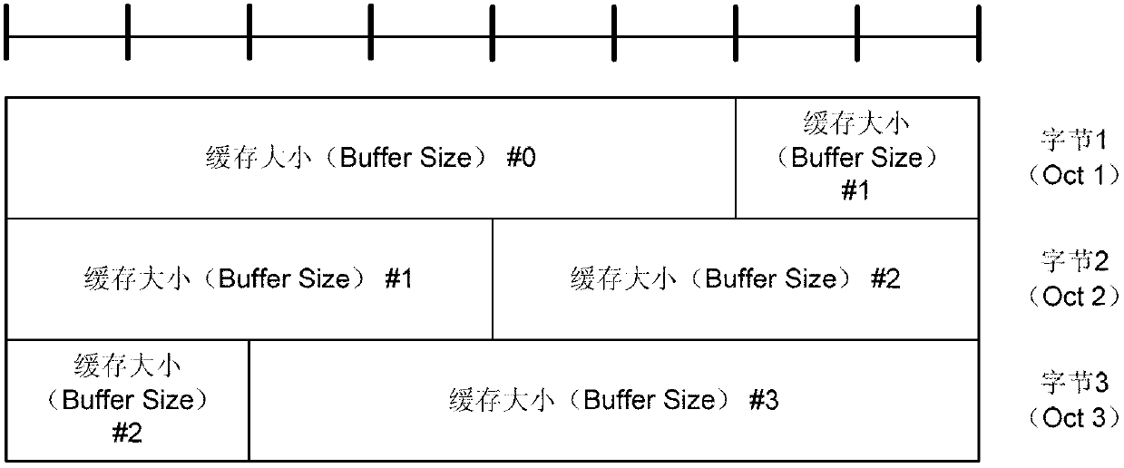
like Figure 1a and Figure 1b As shown, the short BSR reporting only occupies one byte of overhead, while the long BSR will occupy 3 bytes of overhead. If some services with the same characteristics are set to different logical channel groups, the UE will have to report the long BSR , resulting in a waste of system air interface resources
[0010] Second: setting the same logical channel group for services with very different QoS characteristics will not be conducive to eNB resource allocation
[0011] Third: setting the same logical channel group for services with too much difference in bit rate requirements will not be conducive to eNB's accurate grasp of different service data cache sizes and resource allocation
If services with very different bit rate requirements are set to the same logical channel group, such an excessively large buffer data dynamic range will not be conducive to the eNB's accurate grasp of low bit rate services and resource allocation. When system resources are tight, excessive allocation will occur. Resources will be wasted, resource allocation is too low, and high-priority business QoS may not be reasonably guaranteed

Method used


Image

  • Logical channel grouping method in LTE system
  • Logical channel grouping method in LTE system
  • Logical channel grouping method in LTE system

Examples


Embodiment Construction

[0032] The following three uplink logical channels are defined in the LTE system:

[0033] Common Control Channel (CCCH): Used to transmit control information. When the UE does not establish an RRC connection with the network, this channel is used. Since the CCCH channel is used before the RRC connection is established, there is no need for BSR reporting or logical channels. group;

[0034] Dedicated Control Channel (DCCH): A point-to-point bidirectional channel used to transmit dedicated control information. This channel is used when the UE has an RRC connection;

[0035] Dedicated Traffic Channel (DTCH): DTCH is a point-to-point channel, dedicated to one UE, used to transmit user information, and can be bidirectional. The data service used for DTCH transmission has 9 levels according to different QoS class identifier (QCI) characteristics, as shown in Table 2:

[0036]

[0037] Table 2

[0038] The logical channel grouping method in the LTE system proposed by the prese...


PUM


Abstract

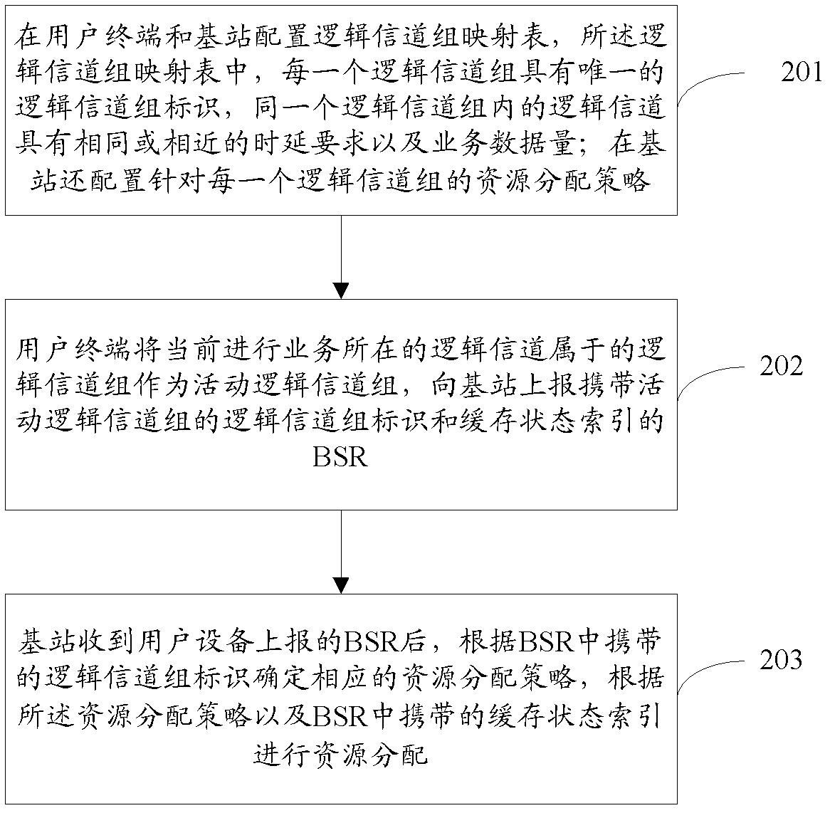
The invention provides a logical channel grouping method in an LTE system. A logical channel group mapping table is configured in a user terminal and a base station, and in the logical channel group mapping table, each logical channel group has a unique logical channel group identifier, and logical channels within a same logical channel group have the same or similar delay requirement and service data size; a resource allocation strategy for each logical channel group is configured in the base station; the user terminal takes a logical channel group, to which a logical channel where a currently-performed service is located belongs, as a mobile logical channel group, and reports to the base station a buffer status report (BSR) carrying a logical channel group identifier of the mobile logical channel group and a buffer status index; and the base station determines a corresponding resource allocation strategy according to the logical channel group identifier carried in the BSR and carries out resource allocation according to the resource allocation strategy and the buffer status index carried in the BSR after receiving the BSR reported by the user equipment.

Description

technical field [0001] The invention relates to the technical field of mobile communication, in particular to a logical channel grouping method in an LTE system. Background technique [0002] In the LTE system, in order to assist the base station (eNB) in uplink resource allocation and scheduling, the protocol stipulates that the user equipment (UE) should trigger buffer status reports periodically or aperiodically, so that the eNB can grasp the resource requirements of the UE in a timely manner and accurately And the time-frequency resource required by the service is allocated to the UE in a timely manner. [0003] Since the UE can perform multiple services at the same time, and different services have different QoS requirements, in principle, the UE needs to report the buffer data size of the logical channel where each service is located, which will bring a lot of overhead. In order to save air interface resources, the LTE protocol defines a logical channel group, and dif...

Claims


Application Information

Patent Timeline
IPC IPC(8): H04W72/04H04W72/10H04L5/00H04L1/00
Inventor 姚燕玲
Owner POTEVIO INFORMATION TECH
Learn More