
Multi-directional racetrack rotating cathode for PVD array applications

一种旋转靶、旋转轴的技术,应用在真空蒸发镀覆、涂层、放电管等方向,能够解决易于出错、耗时、可动磁棒或磁轭成本密集等问题

Active Publication Date: 2017-03-29
APPLIED MATERIALS INC
View PDF3 Cites 0 Cited by
  • Summary
  • Abstract
  • Description
  • Claims
  • Application Information

AI Technical Summary

Problems solved by technology

[0006] However, movable bar magnets or yokes are cost-intensive and error-prone because movement of the bar magnet, such as rotation, is time-consuming and bar movement requires extensive hardware as well as software effort to drive the magnet assembly

Method used


Image

  • Multi-directional racetrack rotating cathode for PVD array applications
  • Multi-directional racetrack rotating cathode for PVD array applications
  • Multi-directional racetrack rotating cathode for PVD array applications

Examples


Embodiment Construction

[0024] Reference will now be made in detail to various embodiments of the invention, one or more examples of which are illustrated in the accompanying drawings. In the following description of the figures, the same reference numerals represent the same components. In general, only the differences with respect to the respective embodiments are described. Each example is provided by way of explanation of the invention, and each example is not meant as a limitation of the invention. Furthermore, features illustrated or described as part of one embodiment can be used on or in conjunction with other embodiments to yield a still further embodiment. This description is intended to cover such modifications and variations.

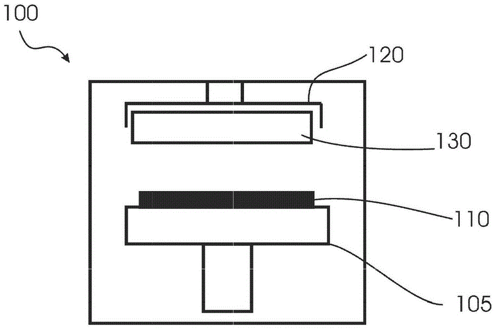
[0025] figure 1 Illustrated is a deposition chamber suitable for a PVD process according to embodiments described herein. Typically, the chamber 100 includes a substrate support 105 adapted to transfer a substrate 110 . Furthermore, the chamber 100 includes a ...


PUM


Abstract

A cathode assembly (130, 200, 300, 400) for a sputter deposition apparatus and a method for coating a substrate are provided. The cathode assembly has a coating side for coating on a substrate. Furthermore, the cathode assembly comprises: a rotating target assembly adapted to rotate the target material (210, 310, 410) about an axis of rotation (220, 320, 420); at least one first magnet assembly (230, 330, 340 , 430, 431, 432, 433), the at least one first magnet assembly has an inner magnetic pole and at least one outer magnetic pole and is adapted to generate one or more plasma regions (240, 250, 340, 350, 440, 441, 442, 443). The cathode assembly (130, 200, 300, 400) has a first angular coordinate for one pole, which is provided for the coating side, and a second angular coordinate for the other pole, which is provided for For the coating side; wherein the first angular coordinate (260, 360, 460) and the second angular coordinate (270, 370, 461) define an angle α greater than about 20 degrees and less than about 160 degrees.

Description

technical field [0001] Embodiments of the invention relate to cathode assemblies for deposition apparatus and methods for depositing thin films on substrates. Embodiments of the invention particularly relate to cathode assemblies for sputter deposition apparatuses, and methods for depositing thin films on substrates in sputter deposition apparatuses. In particular, embodiments relate to cathode assemblies having magnet assemblies and methods for depositing thin films using magnetic fields. Background technique [0002] Coating materials are useful in some applications and in some technical fields. For example, substrates for displays are often coated using a physical vapor deposition (PVD) process. Further applications of coating materials include heat shields, organic light-emitting diode (OLED) panels, and hard disks, CDs, DVDs, etc. [0003] Several methods are known for coating substrates. For example, the substrate may be coated by a PVD process, a chemical vapor de...

Claims


Application Information

Patent Timeline
Patent Type & Authority Patents(China)
IPC IPC(8): C23C14/34C23C14/35H01J37/34
CPCC23C14/3407C23C14/35H01J37/3452H01J37/3405H01J37/345H01J37/3455H01J37/32532
Inventor E·谢尔M·哈尼卡R·林德伯格M·班德尔A·洛珀K·施沃恩特兹F·皮耶拉利西J·刘
Owner APPLIED MATERIALS INC
Learn More