Anti-follow-up monitoring and lighting integrated device for medical pendant

A pendant, follow-up technology, applied in applications, medical science, hospital equipment, etc., can solve the problems of inconvenient operation, inability to adjust the position with the progress of the operation, loss of monitoring function of the monitoring camera, etc., to prevent the boom. Follow-up with the beam, increase the dynamic monitoring range, clear lighting and monitoring effects

Inactive Publication Date: 2015-09-30
BEIJING AEONMED
View PDF6 Cites 0 Cited by
  • Summary
  • Abstract
  • Description
  • Claims
  • Application Information

AI Technical Summary

Problems solved by technology

[0005] At present, most of the lighting devices of medical pendants on the market use a simple rotating arm to connect the lighting device. Some medical pendants equipped with monitoring cameras also fix the camera at a certain position of the medical pendant. The existing problems are : When the ambient light is insufficient or the lighting device rotates and lifts away from the monitoring area, the lighting light is insufficient, so that the monitoring function of the monitoring camera is basically lost; most of the rotating arms of the lighting device are directly connected and fixed with the beam of the pendant tower, which makes when When the beam of the pendant tower rotates and moves, the lighting device will follow. When the beam of the pendant tower rotates to the working position, the specific position of the lighting device must be adjusted again through the rotating arm, which is very inconvenient to operate; the monitoring camera is fixed on a certain part of the pendant tower. One position, the monitoring area is limited, and the position cannot be adjusted as the operation proceeds, which often causes medical staff to block the monitoring area during the operation, greatly reducing the effect of the monitoring camera
[0006] For example, the Chinese patent document CN201168058Y discloses a medical pendant equipped with a rotating arm type treatment lighting device, which fixes a fixed joint seat through the lower end of the cross arm, and fixes the monitoring camera under the fixed joint seat so that it faces the The position of the operating table, and then install the lifting arm with the lighting on the fixed joint base through the first joint and the second joint, and realize the rotation and adjustment of the horizontal position of the lighting through the first joint and the second joint, and then through the rotating shaft Further adjusting the vertical position of the lighting lamp basically realizes the pendant design integrating lighting and monitoring equipment, and has certain functions of surgical monitoring and adjustable lighting, but it also has certain defects: first , the monitoring camera is fixedly installed under the fixed joint seat, which only has the function of monitoring directly below, and does not have the function of adjusting the position. When the operation is in progress, the medical staff will inevitably block the monitoring area, resulting in a blind area of ​​monitoring; secondly , the lighting is installed on the fixed joint seat, and the fixed joint seat is fixedly connected with the cross arm, so that when the cross arm rotates, the lighting equipment will follow. When the cross arm is adjusted, the lighting equipment must be adjusted It is inconvenient to adjust again; finally, because the lighting equipment is connected to the fixed joint seat through one joint and two joints, there are certain position restrictions when adjusting the position, and it is difficult to achieve 360° lighting position adjustment

Method used


Image

  • Anti-follow-up monitoring and lighting integrated device for medical pendant
  • Anti-follow-up monitoring and lighting integrated device for medical pendant
  • Anti-follow-up monitoring and lighting integrated device for medical pendant

Examples


Embodiment Construction

[0030] The technical solutions of the present invention will be further described below in conjunction with the accompanying drawings and through specific implementation methods.

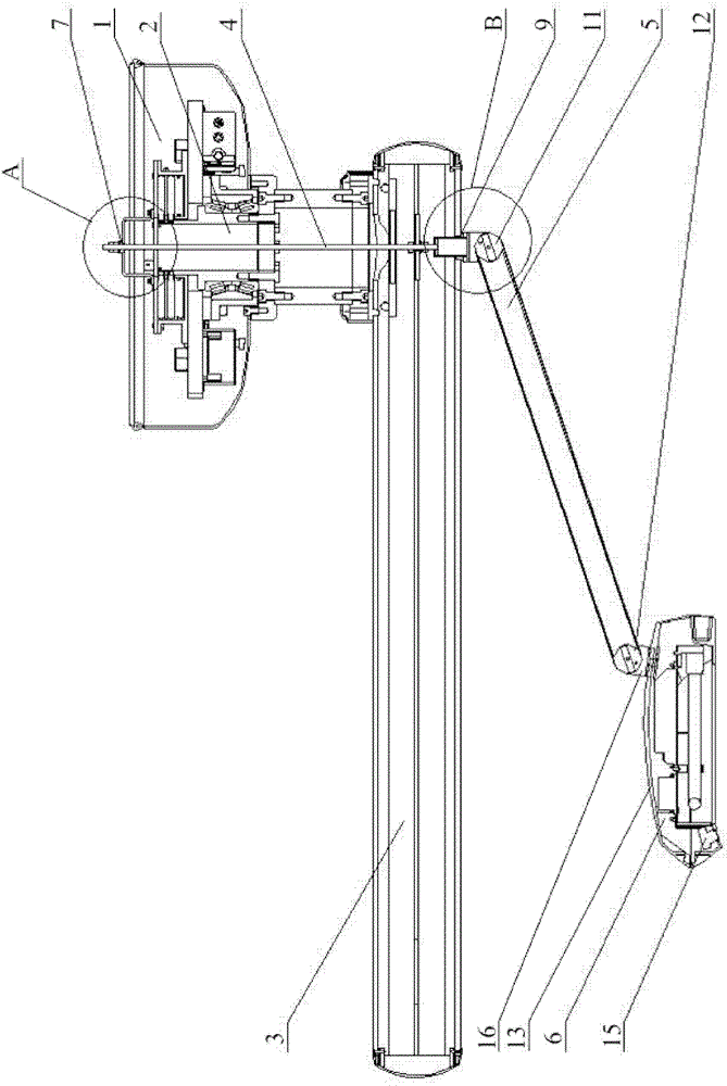
[0031] Such as figure 1 As shown, the anti-follow-up monitoring and lighting integrated device for the medical pendant includes a pendant fixing base 1, a beam rotating shaft 2 and a beam 3, the beam 3 is hinged with the pendant fixing base 1 through the beam rotating shaft 2, and the beam rotating shaft 2 The middle part is provided with a suspender 4, and the suspender 4 is arranged coaxially with the beam rotating shaft 2, and its upper end passes through the suspension tower fixing base 1, and its lower end passes through the cross beam 3.

[0032] A resistance increasing device (that is, a device for increasing the frictional resistance between the boom 4 and the hanger mount 1) is provided at the joint between the boom 4 and the hanger mount 1, so that when the crossbeam 3 rotates, the crossbe...


PUM


Abstract

The invention discloses an all-in-one follow-up prevention monitoring and lighting integral device for a medical tower crane, which comprises a tower crane fixing base, a crossbeam revolving shaft, and a crossbeam, wherein the crossbeam is hinged to the tower crane fixing base through the crossbeam revolving shaft, a hanger rod is arranged at the middle part of the crossbeam revolving shaft and is coaxially arranged with the crossbeam revolving shaft, the upper end of the hanger rod penetrates the tower crane fixing base, the lower end of the hanger rod penetrates the crossbeam; a drag device is arranged at the connecting part of the hanger rod and the tower crane fixing base, so as not to enable the friction force between the crossbeam revolving shaft and the hanger rod to be to drive the hanger rod to flow up when the crossbeam rotates; the lower end of the hanger rod is hinged to one end of a support arm, the other end of the support arm is hinged to a monitoring and lighting device. By the coaxial arrangement of the hanger rod and the crossbeam revolving shaft, separate rotating and adjusting of the monitoring and lighting device and the crossbeam is realized, the arrangement of the drag device effectively avoids a follow-up phenomenon, and the device has the advantages of convenience in operation, and no dead angle in monitoring and lighting.

Description

technical field [0001] The invention relates to a monitoring and lighting device for a medical pendant, in particular to an anti-following monitoring and lighting integrated device for a medical pendant. Background technique [0002] As we all know, the pendant is an indispensable medical equipment in the modern operating room of the hospital. It is mainly used for terminal transfer of oxygen supply, suction, compressed air, nitrogen and other medical gases in the operating room, and provides circuit output and placement of surgical equipment. [0003] With the continuous development of science and technology, medical equipment is also gradually upgraded and improved. The terminal transfer of oxygen supply, suction, compressed air, nitrogen and other medical gases provided by the traditional pendant tower, as well as the circuit output and the placement of surgical equipment are no longer possible. Meet the needs of modern operating rooms. [0004] The traditional pendant m...

Claims


Application Information

Patent Timeline
Patent Type & Authority Patents(China)
IPC IPC(8): A61B19/00G03B15/03H04N5/225A61B90/00A61G12/00
Inventor 吴满立刘丽君
Owner BEIJING AEONMED
Why Eureka
Try Eureka