Unlock instant, AI-driven research and patent intelligence for your innovation.

Force generation device

A technology for generating devices, pressure, applied in the direction of positioning devices, components of pumping devices for elastic fluids, transportation and packaging, etc.

Inactive Publication Date: 2013-09-25
LIUZHOU ZHONGJING TECH
View PDF15 Cites 8 Cited by
  • Summary
  • Abstract
  • Description
  • Claims
  • Application Information

AI Technical Summary

Problems solved by technology

However, because it is a non-contact force application method, there is no contact between the object and the device, so we have no way to directly measure the force acting on the object through conventional means, such as using a force sensor

Method used


Image

  • Force generation device
  • Force generation device
  • Force generation device

Examples


Embodiment 7

[0081] In the non-contact grasping tool in the seventh embodiment, the pressure sensor 27a is set at r m = 0 position to measure the pressure P m1 , the change of the pressure distribution Pi(r) at the radius r=0 is relatively gentle. In this case, the accuracy of the installation position of the pressure sensor is not high, that is to say, a slight deviation in the installation position of the pressure sensor will not affect the The result of pressure distribution calculated by formula (1) has too much influence, and the measured value of pressure P m1 is equal to the coefficient C, which simplifies the calculation process.

[0082] ω 2 The calculation of can be obtained by formula (6):

[0083] ω 2 =2? (P m2 -P m1 ) / r m2 2 ... (6)

[0084] The pressure sensor 27b is installed on r m2 =R 1 The position used to measure the pressure P m2 .

[0085] Calculation unit 28 obtains ω 2 and C, the pressure distributions Pi(r) and Po(r) are calculated based on the formula...


PUM


Abstract

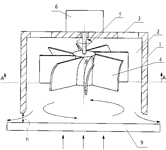
The invention discloses a force generation device, relating to the technical field of production manufacturing. The force generation device has a cup-shaped portion. The cup-shaped portion has a concave portion provided with a cross section of a bottom surface basically being circular, an air suction hole communicated with a bottom port of the concave portion, and a fan blade disposed in the concave portion of the cup-shaped portion. The rotation of the fan blade absorbs air from the air suction hole and generates a rotational flow in the concave portion. A calculation portion for calculating the pressure and force is provided. The calculation portion calculates the pressure and force based on the following formula: Pi (r)=1 / 2pr2omega2+C; in the formula, Pi (r) is a pressure value of the cup-shaped portion at the bottom port of the concave portion and with a distance of r from the rotation center of the fan blade, p is the density of air, omega is the angular speed of the rotational flow, and C is a coefficient. The cup-shaped portion of the force generation device has the calculation portion, and the calculation portion calculates the pressure and force based on the formula in the present invention, so that the user can obtain the condition of the force and pressure.

Description

technical field [0001] The invention relates to the field of manufacturing technology, in particular to a force generating device capable of exerting force on an object without contact. technical background [0002] During the fabrication of semiconductors and glass substrates, there are many tools and equipment designed to grip these workpieces. Previous tools and equipment would touch the workpiece during the gripping process, which would result in scratches on the workpiece and generation of static electricity, resulting in waste and defective products. [0003] Therefore, in recent years, many non-contact gripping tools and equipment have been developed and used in production. For example, the patent "Swirling non-contact suction cup" (publication number: CN101264844, publication date: September 17, 2008), the swirling non-contact suction cup includes: a cup body, a fluid around the inner cavity and a nozzle, wherein: the cup The inside of the body is a cylindrical h...

Claims


Application Information

Patent Timeline
Patent Type & Authority Applications(China)
IPC IPC(8): B65G49/06B65G49/07H01L21/683
CPCB65G47/911H01L21/6838B65G49/061B65G2249/045B23Q3/00B25J15/0616F04D17/10F04D27/001F04D29/4213
Inventor 黎鑫
Owner LIUZHOU ZHONGJING TECH