
Ultrasonic detection device for residual stress on near surface of hole or cavity

A technology of ultrasonic testing and cavities, which can be used in measuring devices, material analysis using sonic/ultrasonic/infrasonic waves, instruments, etc., and can solve problems such as long testing cycles

Active Publication Date: 2013-09-25
BEIJING INSTITUTE OF TECHNOLOGYGY
View PDF10 Cites 9 Cited by
  • Summary
  • Abstract
  • Description
  • Claims
  • Application Information

AI Technical Summary

Problems solved by technology

[0005] For cavity components with large axial dimensions, the test period is long. After the axial position of the stress detection device is fixed, multi-point stress detection in the circumferential direction must be realized. This requires as many sensors as possible to be arranged on the stress detection device. Then the layout, linkage and centering of the sensors become difficult problems

Method used


Image

  • Ultrasonic detection device for residual stress on near surface of hole or cavity
  • Ultrasonic detection device for residual stress on near surface of hole or cavity
  • Ultrasonic detection device for residual stress on near surface of hole or cavity

Examples


Embodiment Construction

[0013] The specific embodiment of the present invention is described in detail below:

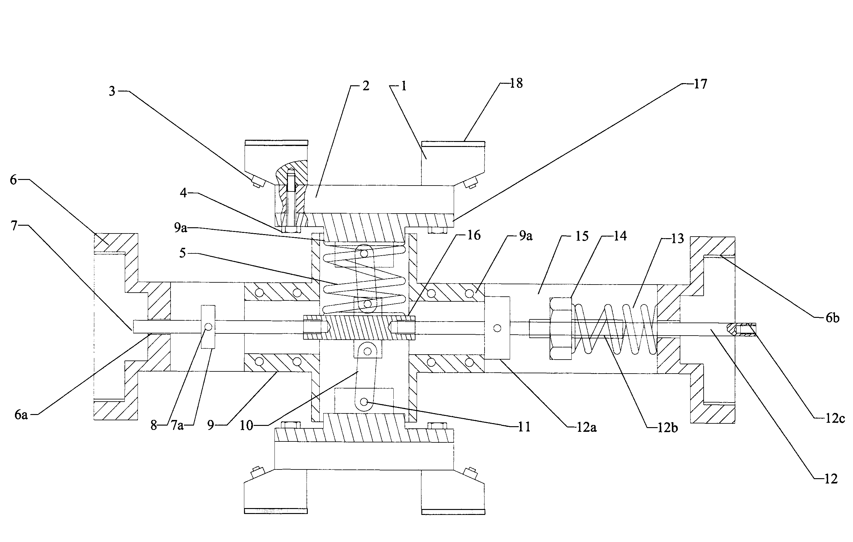
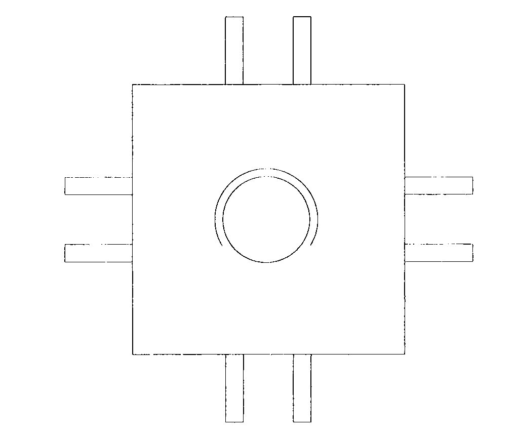
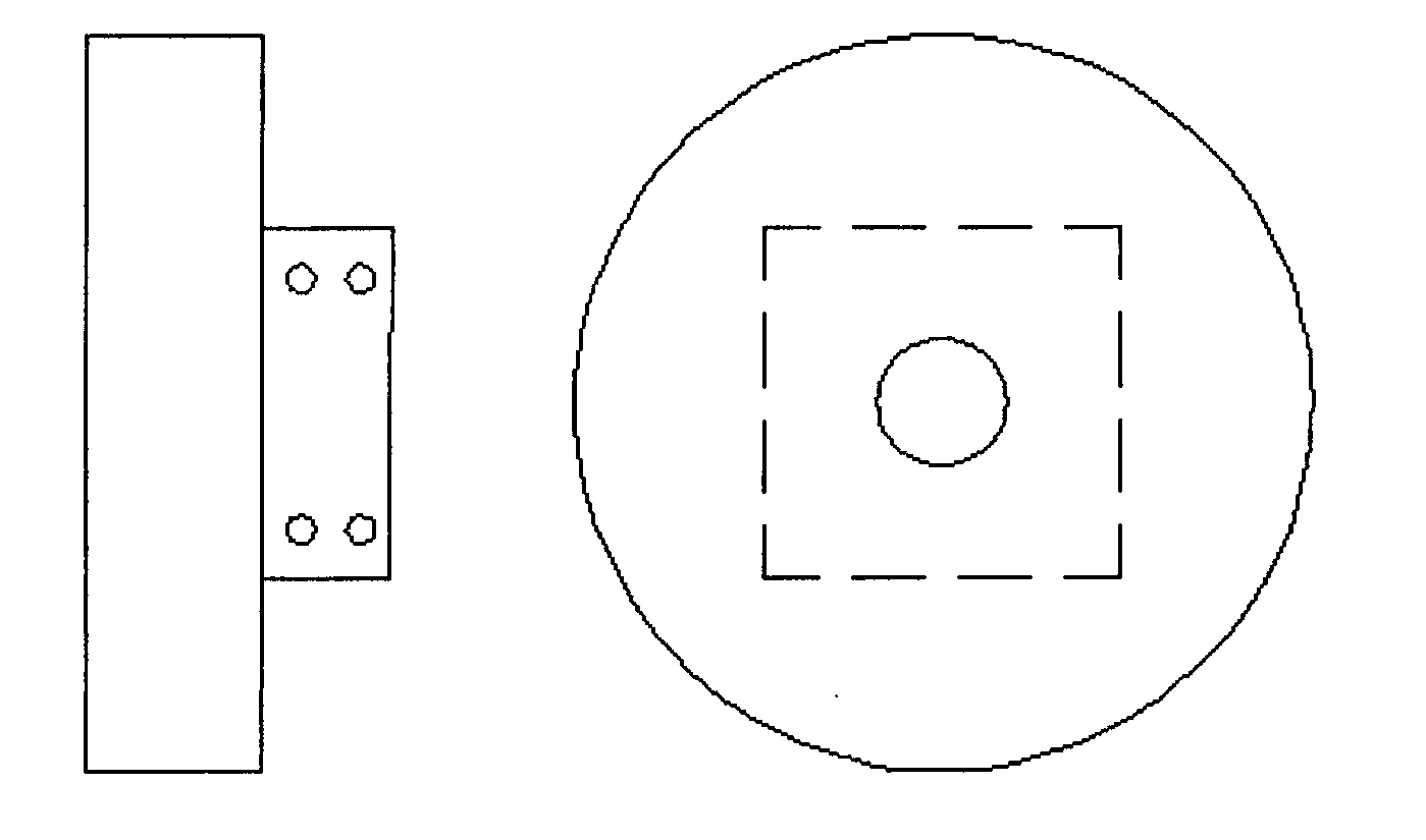
[0014] figure 1 It is a cross-sectional view of the ultrasonic detection device for internal stress of the cavity along its center line of the present invention. as it should figure 1 As shown, the ultrasonic testing device for internal stress in the cavity has 4 sets of transceiver devices (only 2 are shown in the figure), and the transceiver devices are arranged at an angle of 90°. Device 3, screw 4 and silica gel layer 18 are combined. The annular array structure can realize multi-point testing, and it is easy to obtain the circumferential distribution of axial stress. The transceiver device is in the mode of sending and receiving, and uses two ultrasonic transducers. The ultrasonic transducer 3 is fixed in the plexiglass wedge 1 through threads, and the top fixing plate 2 fixes the two plexiglass wedges together. During the stress test, the pressure between the wedge and the inner w...


PUM


Abstract

The invention relates to an ultrasonic detection device for residual stress on a near surface of a hole or a cavity, wherein the device uses an array type ultrasonic sensor transmitter-receiver device, and can implement multi-point test of axial stress in a circumferential direction. In addition, dry coupling technology is used to solve a residual stress coupling problem on the surface of the hole or cavity. For reducing abrasion of an organic glass sound wedge, a transmitter-receiver device lifting mechanism is arranged. In a moving process of the stress detection device, the transmitter-receiver device is lifted, thereby avoiding friction between a sound wedge material and the hole or the cavity, and prolonging service life of the sound wedge. Cooperation usage of the detection device and a creep mechanism can implement centering of the device. Driven by an execution structure, the device can measure axial stress at any position in a deep hole. The device has a simple structure, and can effectively and conveniently implement residual stress detection on the near surface of the hole or the cavity.

Description

1. Technical field [0001] The invention relates to an ultrasonic detection device for the residual stress near the surface of a cavity, which is suitable for detecting the residual stress on the surface of the cavity by applying ultrasonic longitudinal waves. 2. Background technology [0002] The detection of residual stress has received more and more attention, but it is difficult to detect the residual stress on the cavity surface with traditional stress detection equipment. Due to the limitations of space and shape, ordinary ultrasonic testing sensors can only detect the stress at the end of the cavity. [0003] A lot of research has been carried out on the ultrasonic stress testing method at home and abroad, but it is mainly based on contact measurement. During the test, a coupling agent must be applied to the surface of the sensor and the test piece. Due to the self-weight and fluidity of the couplant, the coupling effect is poor. In addition, when measuring the inter...

Claims


Application Information

Patent Timeline
Patent Type & Authority Applications(China)
IPC IPC(8): G01N29/265
Inventor 徐春广潘勤学徐浪杨向臣肖定国李骁宋文涛郭军刘海洋
Owner BEIJING INSTITUTE OF TECHNOLOGYGY
Learn More