
Method for time alignment between interference SAR echo data and platform motion and gesture data

A technology of echo data and time alignment, which is applied in radio wave reflection/re-radiation, radio wave measurement system, and utilization of re-radiation, etc., which can solve the problems of difficult time alignment accuracy, motion compensation, and interference with SAR image quality Problems such as digital elevation model accuracy degradation, etc., to achieve the effect of easy grasp and evaluation, and clear physical meaning

Active Publication Date: 2013-09-25
INST OF ELECTRONICS CHINESE ACAD OF SCI
View PDF5 Cites 17 Cited by
  • Summary
  • Abstract
  • Description
  • Claims
  • Application Information

AI Technical Summary

Problems solved by technology

[0004] When the interferometric SAR echo data and platform motion and attitude data are not aligned in time, accurate motion compensation cannot be performed, and additional errors will be introduced, resulting in the degradation of interferometric SAR image quality and digital elevation model accuracy
The current interferometric SAR system usually relies on the GPS time trigger device in the front-end radar equipment to achieve the alignment of the interferometric SAR echo data with the platform motion and attitude data. Accuracy is difficult to guarantee

Method used


Image

  • Method for time alignment between interference SAR echo data and platform motion and gesture data
  • Method for time alignment between interference SAR echo data and platform motion and gesture data
  • Method for time alignment between interference SAR echo data and platform motion and gesture data

Examples


Embodiment Construction

[0025] In order to make the object, technical solution and advantages of the present invention clearer, the present invention will be described in further detail below in conjunction with specific embodiments and with reference to the accompanying drawings.

[0026] It should be noted that, in the drawings or descriptions of the specification, similar or identical parts all use the same figure numbers. And in the drawings, the shapes or thicknesses of the embodiments may be enlarged, and marked for simplicity or convenience. Furthermore, elements or implementations not shown or described in the drawings are forms known to those of ordinary skill in the art. Additionally, while illustrations of parameters including particular values ​​may be provided herein, it should be understood that the parameters need not be exactly equal to the corresponding values, but rather may approximate the corresponding values ​​within acceptable error margins or design constraints.

[0027] In a ...


PUM


Abstract

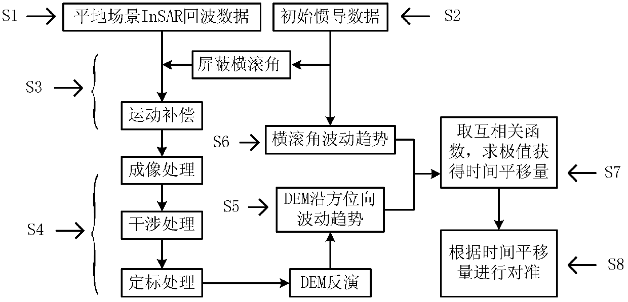
The invention discloses a method for time alignment between interference SAR echo data and platform motion and gesture data. The method comprises the steps of selecting the interference SAR echo data corresponding to a flat ground scene, acquiring the platform motion and gesture data corresponding to the interference SAR echo data and measured by a platform inertial navigation / GPS device, compensating the interference SAR echo data by means of the platform motion and gesture data when a roll angle is 0 degree to further obtain a scene digital elevation model through back analysis, acquiring an elevation azimuth wave function from the scene digital elevation model, acquiring the changing function of the roll angle from the platform motion and gesture data, solving a time value corresponding to the most value of a cross-correlation function of the elevation azimuth wave function and the changing function of the roll angle and taking the time value as time displacement quantity, and carrying out time displacement on the platform motion and gesture data according to the time displacement quantity and achieving the time alignment between the interference SAR echo data and the platform motion and gesture data.

Description

technical field [0001] The invention relates to the technical field of signal processing in the electronic industry, in particular to a time alignment method of interferometric synthetic aperture radar (Synthetic Aperture Radar, SAR) echo data and platform motion and attitude data. Background technique [0002] Synthetic aperture radar is a two-dimensional imaging radar. In the range direction, that is, the beam irradiation direction, the resolution is obtained through time-delay measurement. In the azimuth direction, that is, the direction of platform movement (usually perpendicular to the range direction), the Doppler Beam sharpening for resolution. Synthetic aperture radar needs to be installed on a moving platform, such as an aircraft or a satellite. The motion platform of the airborne synthetic aperture radar is an airplane. Interferometric synthetic aperture radar refers to the use of two or more synthetic aperture radars at different positions to observe the same sc...

Claims


Application Information

Patent Timeline
IPC IPC(8): G01S13/90
Inventor 向茂生毛永飞郭泾平韦立登
Owner INST OF ELECTRONICS CHINESE ACAD OF SCI
Learn More