
Image inversion method of non-uniform sampling comprehensive bore diameter radiometer

A non-uniform sampling, comprehensive aperture technology, applied in the direction of using re-radiation, reflection/re-radiation of radio waves, instruments, etc., can solve the problems of high storage space overhead and low computational efficiency, and achieve small storage space and computational complexity. Low, high precision effects

Active Publication Date: 2013-09-25
HUAZHONG UNIV OF SCI & TECH
View PDF3 Cites 15 Cited by
  • Summary
  • Abstract
  • Description
  • Claims
  • Application Information

AI Technical Summary

Problems solved by technology

[0004] Aiming at the above defects or improvement needs of the prior art, the present invention provides a non-uniform sampling synthetic aperture radiometer image inversion method, the purpose of which is to quickly, efficiently and accurately invert the scene brightness of the non-uniform sampling synthetic aperture radiometer Temperature distribution images, thereby solving the technical problems of low computational efficiency and large storage space overhead of existing inversion methods

Method used


Image

  • Image inversion method of non-uniform sampling comprehensive bore diameter radiometer
  • Image inversion method of non-uniform sampling comprehensive bore diameter radiometer
  • Image inversion method of non-uniform sampling comprehensive bore diameter radiometer

Examples


Embodiment

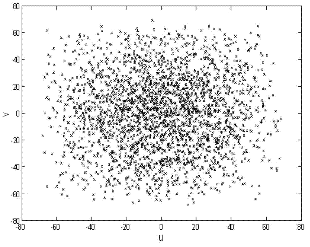
[0046] Embodiment: random sampling synthetic aperture radiometer brightness temperature inversion; in this embodiment, the antenna units are randomly placed in the same plane, and the corresponding sampling points in the spatial frequency domain are also randomly distributed, refer to image 3 .

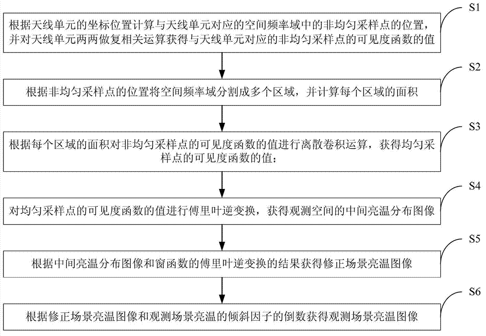
[0047] The specific steps of the image inversion method are as follows: (1) Calculate the corresponding sampling point position (u, v) in the spatial frequency domain according to the position coordinates (x, y) of the antenna unit on the spatial plane, where u=(x i -x j ) / λ, v=(y i -y j ) / λ, where λ is the signal wavelength.

[0048] (2) The spatial frequency domain is divided according to the positions of the sampling points, and the spatial frequency domain is divided into multiple regions. Each region contains only one sampling point and the distance from all points in the region to this sampling point is smaller than the distance to any other sampling point. Segmented spati...


PUM


Abstract

The invention discloses an image inversion method of a non-uniform sampling comprehensive bore diameter radiometer. The image inversion method comprises the steps that the positions of non-uniform sampling points are calculated according to position coordinates of antenna units, and the values of the visibility functions of the non-uniform sampling points are obtained; according to the positions of the non-uniform sampling points, a spatial frequency domain is divided into a plurality of regions, and the area of each region is calculated; according to the area of each region, discrete convolution operation is conducted on the values of the visibility functions of the non-uniform sampling points, and the values of the visibility functions of uniform sampling points are obtained; inverse Fourier transformation is conducted on the values of the visibility functions of the uniform sampling points, and a middle brightness temperature distribution image of an observation space is obtained; according to the middle brightness temperature distribution image and the result of inverse Fourier transformation of a window function, a correction scene brightness temperature image is obtained; according to the correction scene brightness temperature image and the reciprocal of an inclination factor of the observation scene brightness temperature, an observation scene brightness temperature image is obtained. The image inversion method can rapidly, efficiently and accurately achieve inversion of a scene brightness temperature distribution image of the non-uniform sampling comprehensive bore diameter radiometer.

Description

technical field [0001] The invention belongs to the technical field of microwave remote sensing and detection, and more specifically relates to an image inversion method of a non-uniform sampling synthetic aperture radiometer. Background technique [0002] The synthetic aperture radiometer uses multiple discrete small antennas to synthesize an equivalent large antenna aperture, which is arranged in a sparse array to reduce the mass and volume of the antenna and improve the spatial resolution of passive microwave remote sensing. However, this advantage is at the cost of system structure and signal processing complexity, especially for large synthetic aperture systems such as spaceborne synthetic aperture radiometers. Due to the large number of antennas, the system structure and signal processing will be very complicated. In addition, the huge Data volume is also an important issue that cannot be ignored. In addition to the complex structure of the system, the flexibility of ...

Claims


Application Information

Patent Timeline
Patent Type & Authority Applications(China)
IPC IPC(8): G01S13/90
Inventor 李青侠丰励
Owner HUAZHONG UNIV OF SCI & TECH
Learn More