BUCK-BUCK-BOOST bridgeless converter
A BUCK-BUCK-BOOST, converter technology, applied in the field of AC/DC converters, can solve the problems of low efficiency, large common mode current, strong electromagnetic interference, etc. The effect of high circuit reliability
- Summary
- Abstract
- Description
- Claims
- Application Information
AI Technical Summary
Problems solved by technology
Method used
Image


Examples
Embodiment
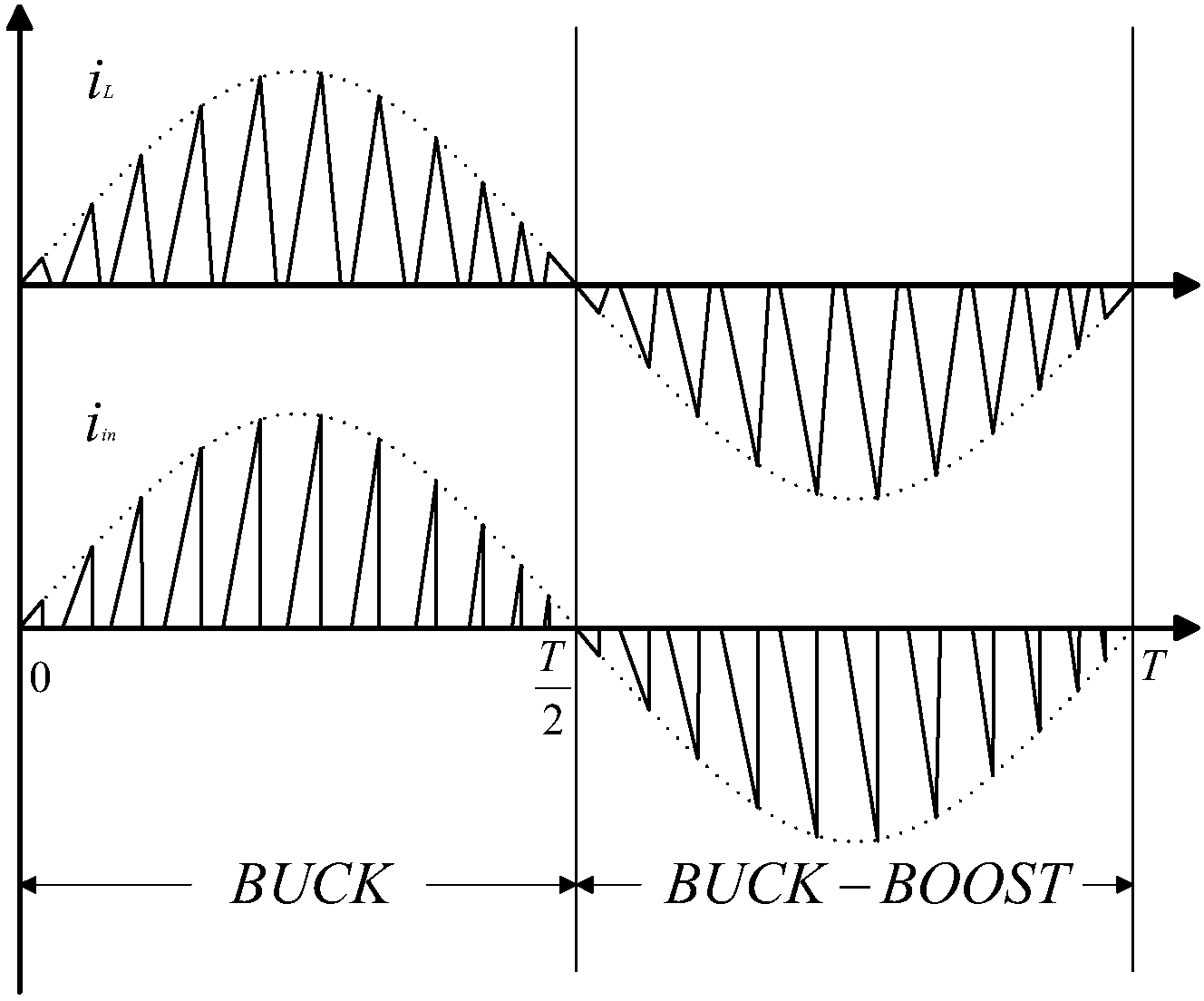
[0016] Such as figure 1 As shown, a BUCK-BUCK-BOOST bridgeless converter is formed by integrating the BUCK circuit link and the BUCK-BOOST circuit link. In the positive half cycle of the input voltage, the circuit works in BUCK mode, and in the negative half cycle of the input voltage, the circuit works in BUCK-BOOST mode.
[0017] The specific circuit includes: input AC power supply, second switch tube S2, inductor L, first diode D1, first switch tube S1, load, capacitor C and second diode D2, the first switch tube S1 The source is respectively connected to the drain of the second switching tube S2 and one end of the input AC power supply, the drain of the first switching tube S1 is respectively connected to one end of the load, one end of the capacitor C, and one end of the inductance L, and the other end of the inductance L respectively connected to the cathode of the first diode D1 and the source of the second switching tube S2; the anode of the second diode D2 is respect...
PUM
 Abstract
Description
Claims
Application Information
 - R&D
- Intellectual Property
- Life Sciences
- Materials
- Tech Scout
- Unparalleled Data Quality
- Higher Quality Content
- 60% Fewer Hallucinations
Browse by: Latest US Patents, China's latest patents, Technical Efficacy Thesaurus, Application Domain, Technology Topic, Popular Technical Reports.
© 2025 PatSnap. All rights reserved.Legal|Privacy policy|Modern Slavery Act Transparency Statement|Sitemap|About US| Contact US: help@patsnap.com