Brake pressure calculation device, brake control system and program
A computing device and brake pressure technology, which can be used in railway brake systems, brakes with brakes, brakes, etc., and can solve problems such as the actual deceleration deviating from the target value
- Summary
- Abstract
- Description
- Claims
- Application Information
AI Technical Summary
Problems solved by technology
Method used
Image

Examples
Embodiment approach 1
[0030] Hereinafter, Embodiment 1 of the present invention will be described. Embodiment 1 is applicable to drive shafts 115 having four shafts ( figure 1 ) of railway vehicles (hereinafter referred to as vehicles). The vehicle includes a body for accommodating passengers, and two carts arranged on the front and rear sides of the lower portion of the body, and two drive shafts 115 are supported on each of the carts. Wheels 116 rolling on rails are attached to both ends of each drive shaft 115 .
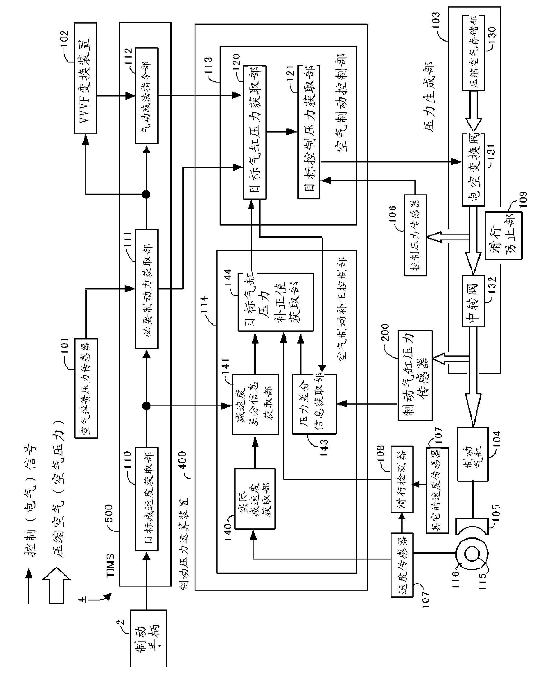
[0031] like figure 1 As shown, the brake control system 1 according to Embodiment 1 includes: a brake pressure calculation device 100 , an air spring pressure sensor 101 , a VVVF (Variable Voltage Variable Frequency) conversion device 102 , a pressure generating unit 103 , a brake cylinder 104 , Brake shoe 105 , control pressure sensor 106 , speed sensor 107 , slip detector 108 , and slip prevention portion 109 . Among them, brake pressure calculation device 100 , pressure genera...
Embodiment approach 2
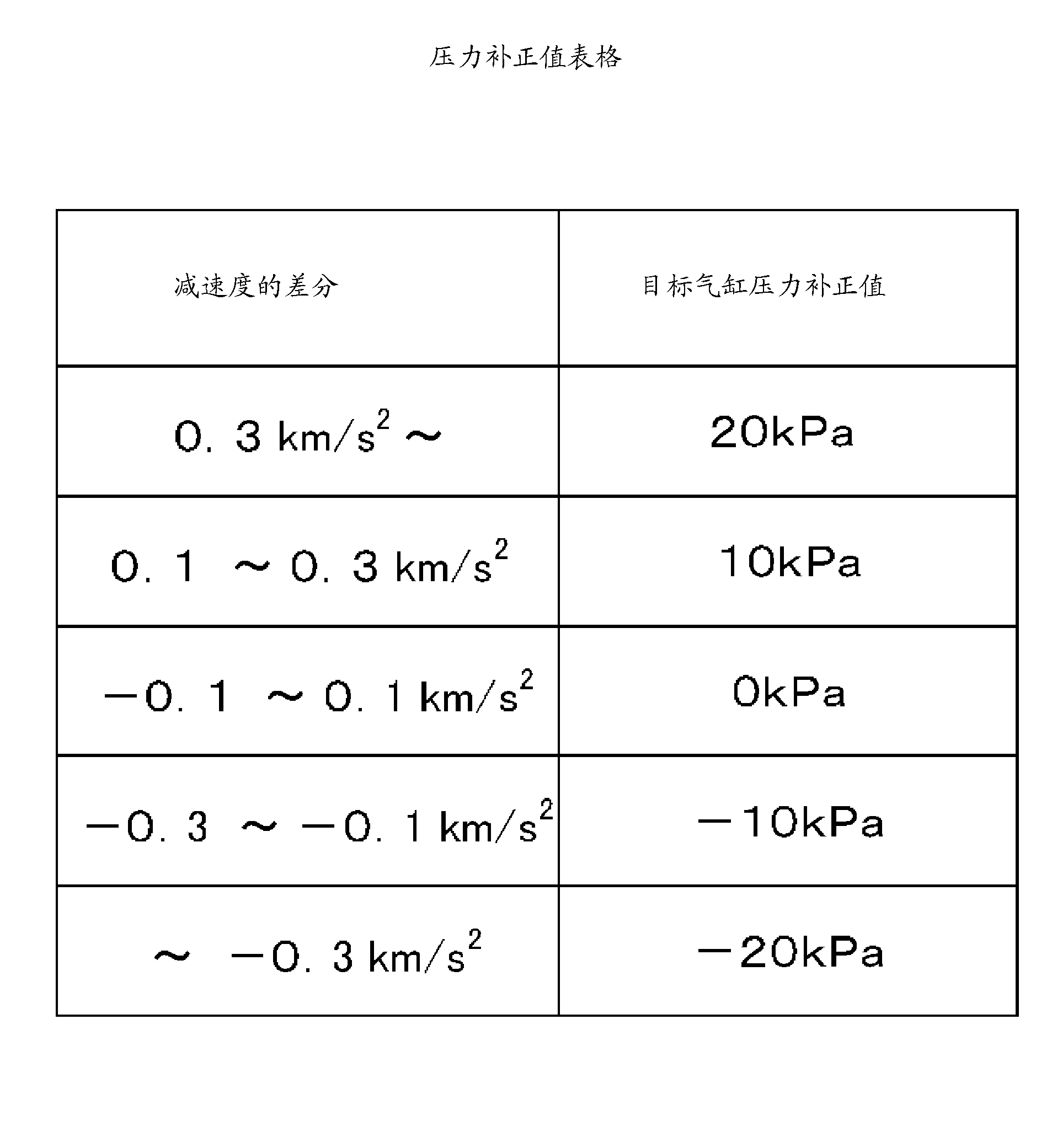
[0078] Next, Embodiment 2 will be described. Embodiment 2 considers that due to the increase in pressure of the transfer valve 132, the lag in response to the cylinder pressure and serpentine movement, wear and thermal deformation on the valve body of the transfer valve 132, and the reduction in the setting accuracy of the cylinder pressure are considered. In addition to the deceleration In addition to the difference, the difference between the target value and the actual value of the cylinder pressure (hereinafter referred to as the difference of the cylinder pressure) is used to obtain the corrected value of the target cylinder pressure.
[0079] Figure 7 The brake control system 3 of the shown embodiment 2 except figure 1 In addition to the structure, a brake cylinder pressure sensor 200 is provided. The brake cylinder pressure sensor 200 is arranged on the pipeline between the relay valve 132 and the brake cylinder 104 . The brake cylinder pressure sensor 200 measures...
Embodiment approach 3
[0136] Next, Embodiment 3 of the present invention will be described. As shown in FIG. 16 , in the brake control system 4 of the present embodiment, the brake pressure calculating device 400 is composed of an air brake control unit 113 and an air brake correction control unit 114 . The target deceleration acquisition unit 110 , the necessary braking force acquisition unit 111 , and the pneumatic subtraction command unit 112 are composed of a TIMS (Train Information Management System) 500 .
[0137] A plurality of brake pressure calculation devices 400 are provided for each self-drive shaft 115 and each other drive shaft 115 . When an abnormality occurs in one of the brake pressure calculation devices 400, the TIMS 500 sends the signals output by the necessary braking force acquisition unit 111 and the pneumatic subtraction command unit 112 (air brake signal and subtraction instruction). The other brake pressure computing device 400 obtains the target cylinder pressure based ...
PUM
 Abstract
Description
Claims
Application Information
 - R&D
- Intellectual Property
- Life Sciences
- Materials
- Tech Scout
- Unparalleled Data Quality
- Higher Quality Content
- 60% Fewer Hallucinations
Browse by: Latest US Patents, China's latest patents, Technical Efficacy Thesaurus, Application Domain, Technology Topic, Popular Technical Reports.
© 2025 PatSnap. All rights reserved.Legal|Privacy policy|Modern Slavery Act Transparency Statement|Sitemap|About US| Contact US: help@patsnap.com