Drive device for a self-propelled machine and corresponding method

A driving device and machine technology, applied in transmission, fluid transmission, transmission control, etc., can solve the problems of driving device installation space requirements, increased manufacturing cost, large size of multi-disc clutch, etc., and achieve the effect of improving life.

Active Publication Date: 2013-09-25
NAF NEUNKIRCHENER ACHSENFABRIK
View PDF7 Cites 0 Cited by
  • Summary
  • Abstract
  • Description
  • Claims
  • Application Information

AI Technical Summary

Problems solved by technology

However, this requires the multi-plate clutch to have relatively large dimensions, whereby the installation space requirement and the manufacturing costs of the drive in turn increase significantly

Method used


Image

  • Drive device for a self-propelled machine and corresponding method
  • Drive device for a self-propelled machine and corresponding method
  • Drive device for a self-propelled machine and corresponding method

Examples


Embodiment Construction

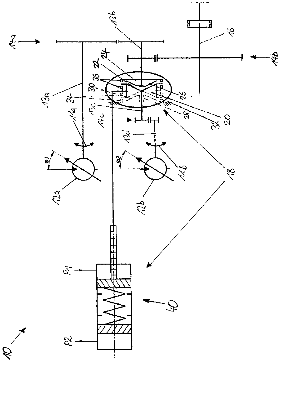
[0037] figure 1 A schematic representation of a drive device 10 according to the invention is shown for a land-based automotive processing machine (not shown). The drive device 10 comprises a first hydraulic motor 12a which can be driven by hydraulic fluid and which is coupled to a driven shaft 16 via a shaft 13a, a gear pair 14a, a shaft 13b and a gear pair 14b. Furthermore, the drive device 10 comprises a second hydraulic motor 12b, which can be driven by hydraulic fluid, and a coupling device 18, via which the second hydraulic motor 12b can be connected to the driven Shaft 16 is coupled for torque boost and is disengageable from driven shaft 16 in the second shift state. The hydraulic motor 12a has a working range which does not allow covering the entire drive range of the high-traction processing machine from low to very high travel speeds. Therefore, the first hydraulic electric motor 12 a is provided for higher speeds and lower tractive forces and is permanently couple...


PUM


Abstract

The invention relates to a drive device (10) comprising a first hydromotor (12a) coupled to an output shaft (16), a second hydromotor (12b), and a coupling device (18) by means of which the second hydromotor (12b) can be coupled to the output shaft (16) in a first switched state for adding torque to the output shaft (16) and decoupled from the output shaft (16) in a second switched state. The coupling device (18) comprises at least one synchronization body (20) coupled to the second hydromotor (12b) and having a conical friction surface (22) and a gear wheel (24) coupled to the output shaft (16) and displaceable relative to the synchronization body (20) and having a corresponding friction surface (26).

Description

technical field [0001] The invention relates to a drive device for an automotive processing machine of the type specified in the preamble of claim 1 . The invention further relates to an automotive working machine with a drive and to a method for operating a drive of an automotive working machine. Background technique [0002] Conventional drives for mobile processing machines are driven by hydraulic motors. However, the operating range of hydraulic motors generally does not allow the entire drive range of the processing machine to be covered from maximum traction at low speeds to maximum travel speed. Therefore, conventional drives have two shifting states, wherein a first shifting state with a larger transmission ratio is suitable for slower speeds and large tractive forces, and a second shifting state with a lower transmission ratio is suitable for For faster speed and less traction. Among them, hydraulic motors are usually kept permanently engaged with a constant gear...

Claims


Application Information

Patent Timeline
Patent Type & Authority Applications(China)
IPC IPC(8): F16H47/02F16H61/30
CPCF16H47/02F16H61/30F16H2047/025F16H2061/307F15B15/1409Y10T74/19014F16H37/065
Inventor B·施纳贝尔
Owner NAF NEUNKIRCHENER ACHSENFABRIK
Why Eureka
Try Eureka