Magnetic control brake device of flywheel of exercise bicycle

A brake device and exercise bike technology, applied in the direction of training equipment for adjusting coordination, training equipment for adjusting the cardiovascular system, gymnastic equipment, etc., can solve problems such as injury to the user's hand, inconvenience in use, and personal injury to the bodybuilder. Achieve the effects of convenient use and maintenance, controllable braking resistance and simple structure

Active Publication Date: 2013-10-02
昆山亚新鸿运动器材有限公司
View PDF7 Cites 11 Cited by
  • Summary
  • Abstract
  • Description
  • Claims
  • Application Information

AI Technical Summary

Problems solved by technology

This kind of braking method has the following defects: usually the quality of the flywheel is relatively large, and when the flywheel is to be stopped at a fast speed, the bodybuilder must use a large pressing force to make the friction assembly and the flywheel squeeze and contact to generate friction, so that the The reaction force generated during the pressing process is very likely to hurt the user's hand, and it is inconvenient to use; moreover, the resistance generated by the friction component to the flywheel cannot be controlled, that is, the speed and degree of braking cannot be controlled; secondly, during the entire braking process, only The resistance is generated by friction components, and long-term contact friction with the flywheel is likely to cause irreversible damage. It needs to be replaced regularly. If it is not replaced in time, it will easily cause personal injury to the bodybuilder in an emergency

Method used


Image

  • Magnetic control brake device of flywheel of exercise bicycle
  • Magnetic control brake device of flywheel of exercise bicycle

Examples


Embodiment Construction

[0027] combine figure 1 with figure 2 The present invention is described in further detail.

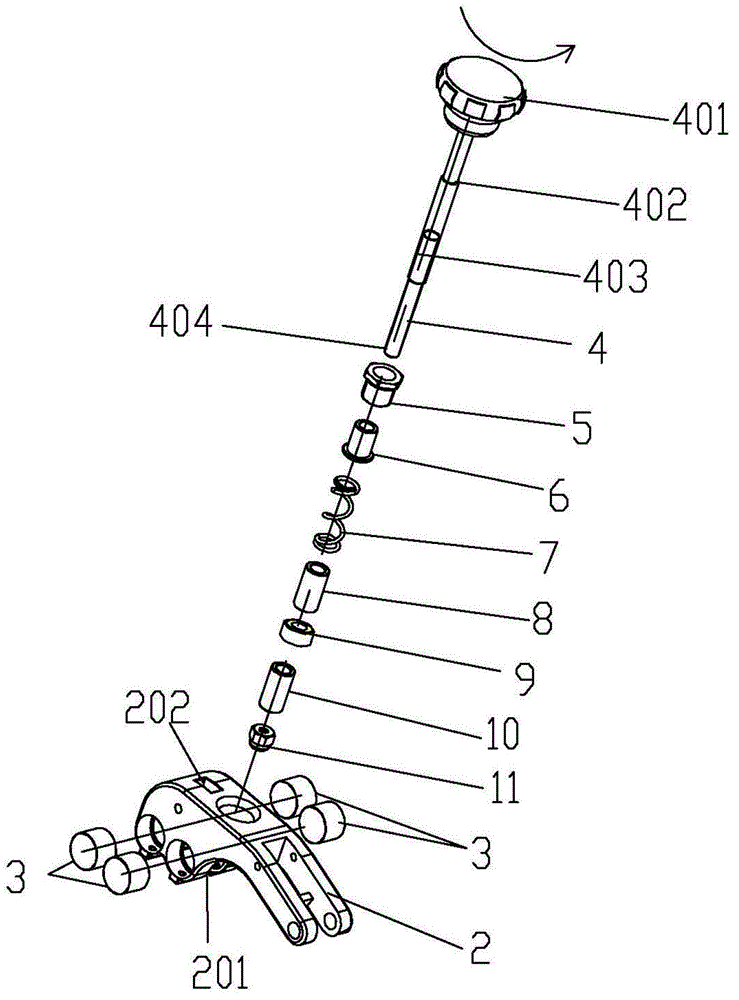
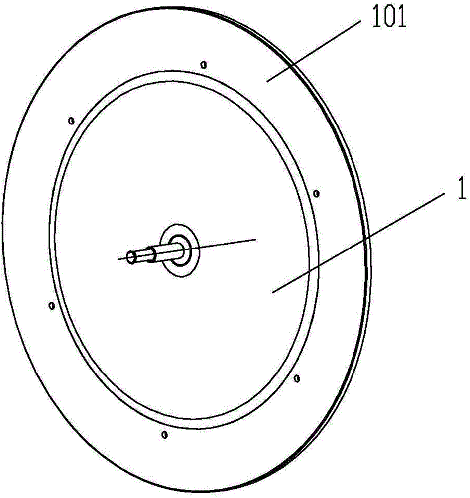
[0028] A magnetically controlled brake device for a flywheel of an exercise bike, comprising a brake adjusting rod assembly passing through a transverse inclined tube of a frame, and a magnetically controlled brake assembly arranged above the flywheel 1 and connected to the frame in movable positioning. Wherein the outer circumference of the flywheel 1 is a metal ring 101 coaxial with the flywheel, and the metal ring is a non-ferromagnetic metal ring structure, such as a smooth aluminum ring or a copper ring, preferably a smooth aluminum ring.

[0029] The magnetic control brake assembly includes a magnetic control base 2 that is movable and positioned on the frame, and is based on the direction when a person is riding. The specific structure of the connection is: the rear end of the magnetic control base 2 is connected by a common method such as thread Fixedly connected on the veh...


PUM


Abstract

The invention discloses a magnetic control brake device of a flywheel of an exercise bicycle. According to the device, the peripheral ring of the flywheel is made of a non-ferrous magnetic metal ring, and then, a plurality of pairs of permanent magnets capable of generating stationary magnetic fields are arranged a U-shaped groove of a magnetic control substrate located above the flywheel, and a brake regulating stem assembly is capable of regulating the position of the magnetic control substrate relative to the flywheel in a vertical direction, so that the depth of the metal ring of the flywheel to enter the U-shaped groove of the magnetic control substrate is controllable. As closed loop-type induced current can be generated in the metal ring when magnetic induction lines of the stationary magnetic fields are cut without stop by the metal ring of the flywheel when the flywheel rotates at a high speed, and the metal ring can be hindered from rotating by interaction forces between the stationary magnetic fields and induced magnetic fields generated by the induced current, the rotation of the flywheel is decelerated and even stopped to reach a brake effect. The brake device has the advantages that the structure is simple, potential damage cannot be caused to hands of an operator, the brake resistance is controllable, and meanwhile, the use and the maintenance are extremely convenient.

Description

technical field [0001] The invention relates to a brake device, in particular to a magnetically controlled brake device for a flywheel of an exercise bike, and belongs to the field of spare parts of the exercise bike. Background technique [0002] With the improvement of people's attention to physical health and the increasingly tight rhythm of daily life, indoor sports are loved by bodybuilders. Among them, exercise bikes have become one of the most popular indoor sports and fitness equipment because of their ease of use and good exercise effects. [0003] The exercise bike allows the bodybuilder to achieve the effect of exercise and fitness by overcoming the resistance brought by the flywheel with a certain weight during the pedaling process to simulate the riding feeling. Its main components include a front standpipe, a rear seat tube, a frame beam connecting the front riser and the rear seat tube, a transmission device and a brake device, and the main components of the t...

Claims


Application Information

Patent Timeline
Patent Type & Authority Applications(China)
IPC IPC(8): A63B22/08
Inventor 吴东勇
Owner 昆山亚新鸿运动器材有限公司
Why Eureka
Try Eureka