
Processing method capable for reducing defective rate of deflecting magnetic core

A processing method and defective rate technology, applied in the manufacture of inductors/transformers/magnets, electrical components, circuits, etc., to achieve the effect of reducing production costs and the method is simple and practical

Inactive Publication Date: 2013-10-02
GUANGYUAN FEIDA MOLD MFG
View PDF2 Cites 0 Cited by
  • Summary
  • Abstract
  • Description
  • Claims
  • Application Information

AI Technical Summary

Problems solved by technology

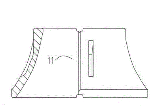
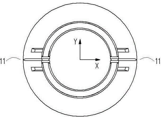
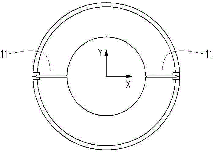
[0002] In the prior art, such as Figure 1 to Figure 3 As shown, the deflection magnetic core product with a tapered sleeve structure is made by powder metallurgy technology. It is first pressed into a prototype with a mold, and then sintered. After sintering, the product has a shrinkage rate of about 1.2%, and the product surface is at X A pair of separation grooves 11 in the axial direction (the separation ribs on the mold correspond to the separation grooves 11, and the product is finally separated into two monomers for use) become the weak point of the entire revolving body, and the shrinkage rate of the weak point area in the X-axis direction is stronger than that in the Y-axis direction rate, resulting in a slight deformation of the rotating body, becoming an ellipse, and the size of the Y-axis direction is 50-56 wires larger than that of the X-axis direction. This size change leads to a 20-30% defective rate in conventional process production

Method used


Image

  • Processing method capable for reducing defective rate of deflecting magnetic core
  • Processing method capable for reducing defective rate of deflecting magnetic core
  • Processing method capable for reducing defective rate of deflecting magnetic core

Examples


Embodiment 1

[0011] Embodiment 1: as Figure 1 to Figure 4 Shown, a kind of embodiment of the present invention comprises the following steps: a, select the die base of the deflection magnetic core die punch; b, adjust the processing size of the die punch and then process the punch: The normal size of the punch hole in the X-axis direction is increased by 50-56 wires, and the punch is processed by the slow wire cutting process, and the X-axis direction where a pair of separation ribs are located is the long axis to process an elliptical cross-sectional structure; c , using the convex mold made in step b to make the deflection magnetic core by conventional pressing process; d, sintering and molding by conventional sintering process.

[0012] The principle is: before sintering, the excessive shrinkage in the X-axis direction (the direction where the pair of separation grooves of the deflection core are located) is reserved through the size adjustment of the mold punch. When pressing the init...


PUM


Abstract

A processing method capable for reducing the defective rate of a deflecting magnetic core comprises the following steps: a, selecting a male die blank of a stamping die for the deflecting magnetic core; b, adjusting the processing size of the male die of the stamping die, and then processing the male die, wherein the conventional size of a rear aperture of the male die of the die in the x-axis direction is enlarged by 50-60 dmm according to different product models, low speed wire-cutting process is adopted for processing the male die to make the male die to be an oval cross section structure, with taking the x-axis direction where a pair of separation ribs are positioned as a major shaft; c, manufacturing the male die obtained in the step b into the deflecting magnetic core in a conventional press process; and d, adopting a conventional sintering process for sintering forming. The method is simple and practical, can reserve the excess shrinkage in the x-axis direction in advance after the completion of the sintering through adjusting the processing size of the male die of the stamping die, solves the problem of high defective rate caused by sintering deformation, allows the defective rate to be around 2 percent, and reduces the manufacturing cost by 25 percent.

Description

technical field [0001] The invention relates to a processing method of a deflection magnetic core, in particular to a processing method capable of reducing the processing defective rate of a deflection magnetic core. Background technique [0002] In the existing technology, such as Figure 1 to Figure 3 As shown, the deflection magnetic core product with a tapered sleeve structure is made by powder metallurgy technology. It is first pressed into a prototype with a mold, and then sintered. After sintering, the product has a shrinkage rate of about 1.2%, and the product surface is at X A pair of separation grooves 11 in the axial direction (the separation ribs on the mold correspond to the separation grooves 11, and the product is finally separated into two monomers for use) become the weak point of the entire revolving body, and the shrinkage rate of the weak point area in the X-axis direction is stronger than that in the Y-axis direction rate, resulting in a slight deformati...

Claims


Application Information

Patent Timeline
Patent Type & Authority Applications(China)
IPC IPC(8): B22F3/03B22F5/10H01F41/02
Inventor 李飞
Owner GUANGYUAN FEIDA MOLD MFG
Learn More