
Novel vibrating burnisher

A technology of finishing machine and vibrating motor, which is applied in the field of finishing machines, can solve the problems of fuzzy workpiece surface, large impact force of grinding media on parts, narrow application range, etc., achieve bright and clear surface, improve finishing effect, and improve application range effect

Active Publication Date: 2013-10-02
HUZHOU XING XING ABRASIVE
View PDF6 Cites 1 Cited by
  • Summary
  • Abstract
  • Description
  • Claims
  • Application Information

AI Technical Summary

Problems solved by technology

[0003] However, the vibration motor configuration of the traditional vibrating finishing machine determines that the grinding medium (also known as the grinding block) rolls spirally in the working tank. Such a vibration curve makes the traditional vibrating finishing machine not only have poor surface finishing effect, but also the workpiece after grinding. The surface is relatively blurred, and even the phenomenon of "orange peel" will appear. It cannot be used for surface finishing treatment on workpieces with high surface requirements (such as automobile wheels), and the application range is narrow. It cannot be used for surface finishing treatment on workpieces with complex structures and large shapes. deal with
In addition, the vibration motor configuration of the traditional vibrating finishing machine has low vibration frequency and large amplitude, which makes the impact force of the grinding medium on the parts larger, which is another reason for the poor finishing effect; for some workpieces with soft materials Surface finishing treatment may directly lead to the damage of the workpiece, which also limits the application range of the vibration finishing machine to a certain extent

Method used


Image

  • Novel vibrating burnisher
  • Novel vibrating burnisher
  • Novel vibrating burnisher

Examples


Embodiment 1

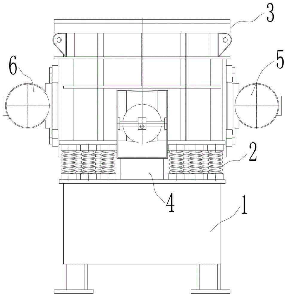
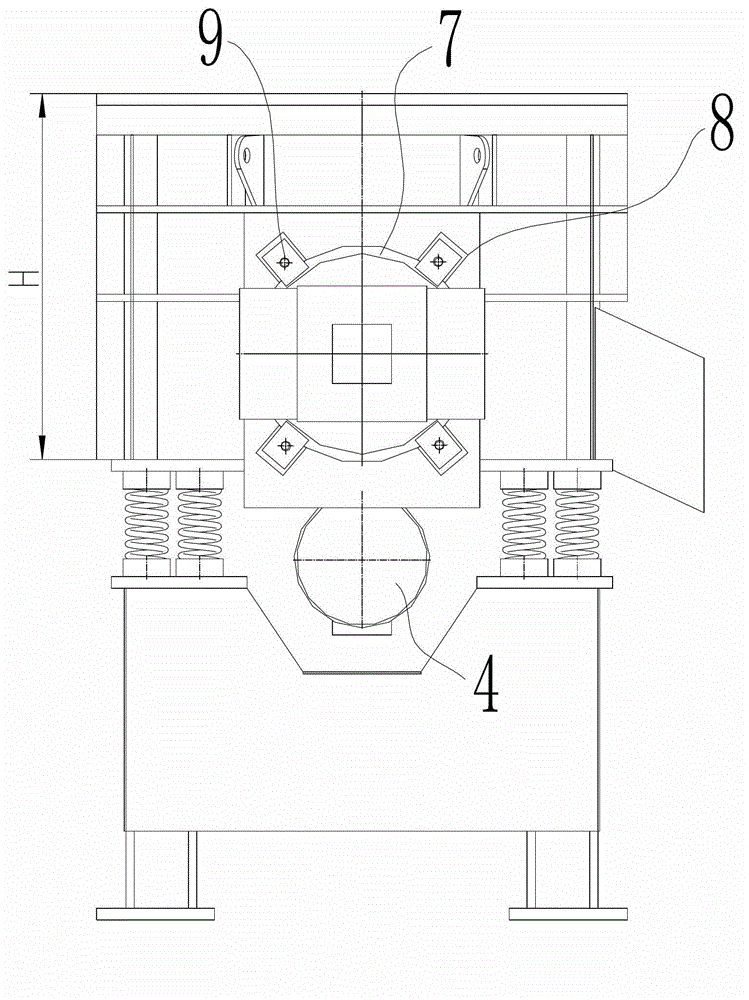
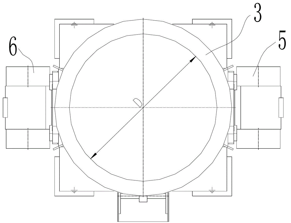
[0020] Example 1. A new type of vibration finishing machine, such as figure 1 , figure 2 and image 3 As shown, it includes a base 1, a spring group 2 is arranged on the base 1, and a working groove 3 is arranged above the spring group 2; its characteristic is: it also includes a first horizontal vibration motor 4 arranged at the bottom of the working groove 3 and symmetrically arranged The second horizontal vibrating motor 5 and the third horizontal vibrating motor 6 on both sides of the working tank 3 .

[0021] The container diameter D of the working tank 3 is 800mm, and the container height H is 650mm; the single power of the three horizontal vibrating motors is 2Kw.

[0022] Such as Figure 4 As shown, the second horizontal vibration motor 5 and the third horizontal vibration motor 6 are both arranged on the side of the working tank 3 through a 360-degree rotating structure. The 360-degree rotating structure includes a flange 7 for installing a vibration motor and a...

Embodiment 2

[0024] Example 2. A new type of vibration finishing machine, such as figure 1 , figure 2 and image 3 As shown, it includes a base 1, a spring group 2 is arranged on the base 1, and a working groove 3 is arranged above the spring group 2; its characteristic is: it also includes a first horizontal vibration motor 4 arranged at the bottom of the working groove 3 and symmetrically arranged The second horizontal vibrating motor 5 and the third horizontal vibrating motor 6 on both sides of the working tank 3 .

[0025] The container diameter D of the working tank 3 is 600 mm, and the container height H is 470 mm; the single power of the three horizontal vibration motors is 1.1 Kw.

[0026] Such as Figure 4 As shown, the second horizontal vibration motor 5 and the third horizontal vibration motor 6 are both arranged on the side of the working tank 3 through a 360-degree rotating structure. The 360-degree rotating structure includes a flange 7 for installing a vibration motor ...

Embodiment 3

[0028] Example 3. A new type of vibration finishing machine, such as figure 1 , figure 2 and image 3 As shown, it includes a base 1, a spring group 2 is arranged on the base 1, and a working groove 3 is arranged above the spring group 2; its characteristic is: it also includes a first horizontal vibration motor 4 arranged at the bottom of the working groove 3 and symmetrically arranged The second horizontal vibrating motor 5 and the third horizontal vibrating motor 6 on both sides of the working tank 3 .

[0029] The container diameter D of the working tank 3 is 1000 mm, and the container height H is 800 mm; the single power of the three horizontal vibration motors is 5.5 Kw.

[0030] Such as Figure 4 As shown, the second horizontal vibration motor 5 and the third horizontal vibration motor 6 are both arranged on the side of the working tank 3 through a 360-degree rotating structure. The 360-degree rotating structure includes a flange 7 for installing a vibration motor...


PUM


Abstract

The invention discloses a novel vibrating burnisher, which comprises a base (1). A spring set (2) is arranged on the base (1). A working groove (3) is formed above the spring set (2). The novel vibrating burnisher is characterized by also comprising a first horizontal vibrating motor (4), a second horizontal vibrating motor (5) and a third horizontal vibrating motor (6), wherein the first horizontal vibrating motor (4) is arranged at the bottom of the working groove (3); and the second horizontal vibrating motor (5) and the third horizontal vibrating motor (6) are symmetrically arranged on the two sides of the working groove (3). Due to the adoption of a novel motor configuration, the novel vibrating burnisher can be used for performing surface burnishing treatment on a workpiece with higher surface finish, is wide in application range, and can be used for performing the surface burnishing treatment on a larger and softer workpiece with a complex structure.

Description

technical field [0001] The invention relates to a novel vibration finishing machine, which belongs to the field of finishing machines. Background technique [0002] With the advancement of science and technology and the development of production, people have higher and higher requirements for the surface quality of mechanical parts, especially in the fields of aerospace, machine tools, automobiles and instrumentation, etc., the surface of mechanical parts is required to have perfect shape and excellent quality. physical properties. [0003] However, the vibration motor configuration of the traditional vibrating finishing machine determines that the grinding medium (also known as the grinding block) rolls spirally in the working tank. Such a vibration curve makes the traditional vibrating finishing machine not only have poor surface finishing effect, but also the workpiece after grinding. The surface is relatively blurred, and even the phenomenon of "orange peel" will appear...

Claims


Application Information

Patent Timeline
IPC IPC(8): B24B31/06
Inventor 徐金发
Owner HUZHOU XING XING ABRASIVE
Learn More