Miniaturized flexible micro clamp based on piezoelectric driving

A technology driven by piezoelectric ceramics and piezoelectric ceramics, applied in the direction of collets, micro manipulators, manipulators, etc., can solve problems such as optical fiber sliding, clamping failure, gas leakage of vacuum suction equipment, etc., to avoid gaps and large displacement output , Guarantee the effect of end grabbing accuracy

Inactive Publication Date: 2013-10-02
BEIHANG UNIV
View PDF6 Cites 40 Cited by
  • Summary
  • Abstract
  • Description
  • Claims
  • Application Information

AI Technical Summary

Problems solved by technology

In angle clamping, because the clamping end has a certain inclination angle, when clamping an optical fiber with a regular geometry, it is easy to cause the optical fiber to slip; vacuum suction clamping is mainly used for operations on a plane, and objects with irregular planes are likely to cause Air leakage from vacuum suction equipment, which in turn leads to clamping failure

Method used


Image

  • Miniaturized flexible micro clamp based on piezoelectric driving
  • Miniaturized flexible micro clamp based on piezoelectric driving
  • Miniaturized flexible micro clamp based on piezoelectric driving

Examples


Embodiment Construction

[0035] The present invention will be further described in detail below in conjunction with the accompanying drawings.

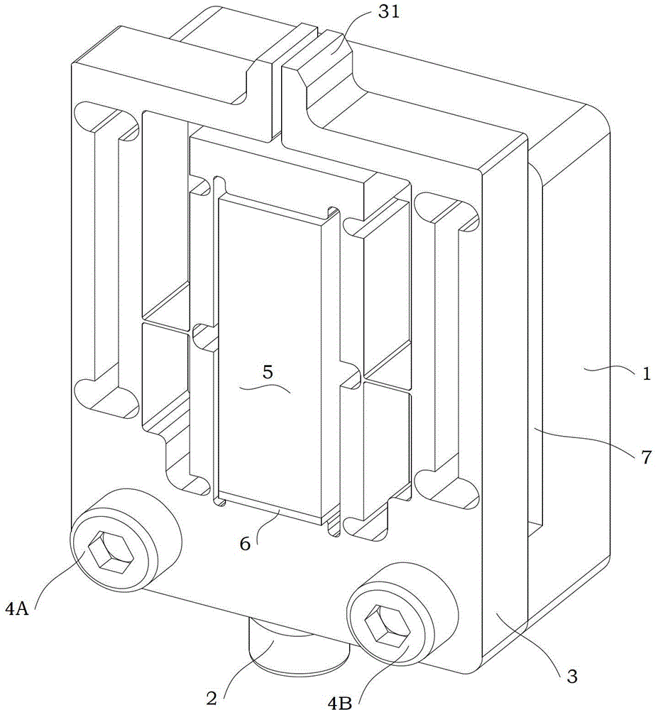
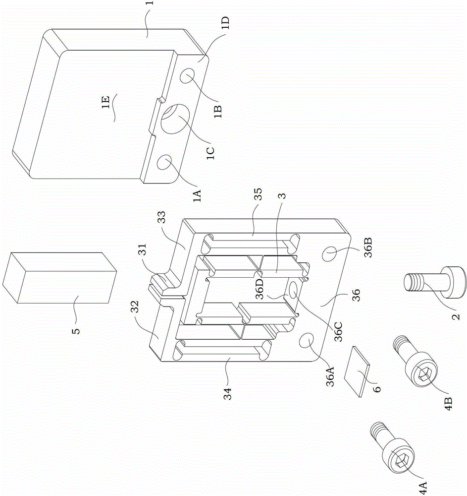
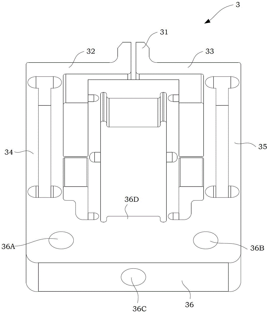
[0036] see figure 1 , Figure 1A As shown, the miniaturized flexible micro-clamp driven by piezoelectric ceramics of the present invention includes a base 1, a pre-tightening screw 2, a motion transmission mechanism 3, a first fixing screw 4A, and a second fixing screw 4B , a piezoelectric ceramic driver 5 and a gasket 6; the base 1 and the motion transmission mechanism 3 are fixedly installed through the first fixing screw 4A and the second fixing screw 4B, and the pre-tightening screw 2 is installed at the rear end of the motion transmission mechanism 3, and the piezoelectric The ceramic driver 5 and the washer 6 are installed in the first slit 351 of the motion transmission mechanism 3 .

[0037] The micro-gripper designed in the present invention can achieve parallel grasping of the closed micro-gripper through the two-stage amplification in the motion ...


PUM


Abstract

The invention discloses a miniaturized flexible micro clamp based on piezoelectric driving. The micro clamp comprises a base, a pretension screw, a motion transmission mechanism, a first fastening screw, a second fastening screw, a piezoceramic driver and a spacer, wherein the base and the motion transmission mechanism are fixedly mounted through the first fastening screw and the second fastening screw; the pretension bolt is arranged at the rear end of the motion transmission mechanism; the piezoceramic driver and the spacer are arranged in a first cutting slot of the motion transmission mechanism. According to the design of the invention, through a two-stage amplification mechanism in the amplification mechanism, the parallel grabbing of the closed-type micro clamp can be realized.

Description

technical field [0001] The invention relates to a clamping device, more particularly, to a miniaturized flexible micro-clamp driven by piezoelectric ceramics. Background technique [0002] At present, micromanipulation and microassembly are widely used in research fields such as microelectromechanical systems, optical fiber assembly, bioengineering, and electronic packaging of small components. Among them, the micro gripper is an important device, which is mainly used to clamp and manipulate micro objects with a diameter of less than 100 microns, such as optical fibers and wood fibers. Due to the unique flexibility of the micro gripper itself, the micro gripper can realize micro operations such as picking up, clamping and moving. [0003] A microgripper usually consists of an actuator and a motion transfer mechanism. At present, the driving methods for micro grippers mainly include electrothermal driving, electromagnetic driving, piezoelectric driving, electrostatic drivin...

Claims


Application Information

Patent Timeline
Patent Type & Authority Applications(China)
IPC IPC(8): B25J7/00B25J15/00
Inventor 孙先涛陈伟海周锐张建斌陈文杰
Owner BEIHANG UNIV
Why Eureka
Try Eureka