
Variable pressure-resistant cascading liquid piston device

A liquid piston, cascading technology, applied in the direction of variable capacity pump components, liquid variable capacity machines, machines/engines, etc., can solve the problems of low efficiency, increased cost, and inability to provide gas temperature control, etc., to reduce pipelines Switching, reducing project cost, and remarkable economic effect

Active Publication Date: 2013-10-02
NORTH CHINA ELECTRIC POWER UNIV (BAODING)
View PDF12 Cites 13 Cited by
  • Summary
  • Abstract
  • Description
  • Claims
  • Application Information

AI Technical Summary

Problems solved by technology

However, traditional compressed air energy storage has certain limitations. Traditional compressed air energy storage is usually combined with turbomachinery. Turbomachinery is less efficient for gases with rapidly changing pressures and cannot provide temperature control of the gas.
[0003] In recent years, there have been researches on applying liquid pistons to compressed air energy storage, which solved the efficiency problem caused by rapid pressure changes when compressing air, but each liquid piston chamber is realized by a pressure vessel, and its compressive strength is given by The maximum pressure of the compressed gas is determined, and its disadvantage is that if the capacity of the liquid piston chamber is enlarged, the cost will be greatly increased

Method used

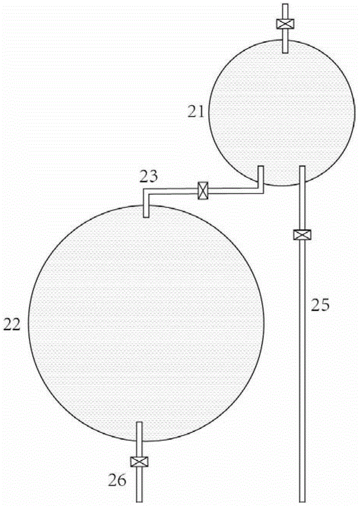
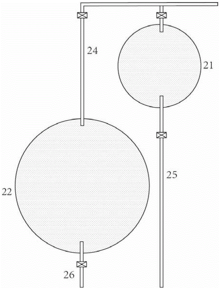

Image

  • Variable pressure-resistant cascading liquid piston device
  • Variable pressure-resistant cascading liquid piston device
  • Variable pressure-resistant cascading liquid piston device

Examples


Embodiment Construction

[0037] The present invention provides a variable pressure-resistant cascaded liquid piston device. The present invention will be further described below in conjunction with the accompanying drawings and specific embodiments.

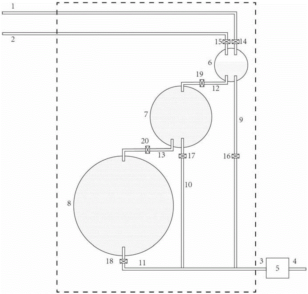
[0038] figure 1 Shown is a general structure diagram of a liquid piston device. The three pressure vessels 6, 7 and 8 with different pressure resistance values ​​in the device are connected to each other to form a pressure vessel group, in which the pressure vessel 6 has the highest pressure resistance level and the smallest volume; the pressure vessel 8 has the lowest pressure resistance level and the largest volume . There are fast liquid pipelines 9, 10 and 11 at the bottom of the three pressure vessels respectively, and the fast liquid pipelines are connected with the external hydraulic equipment 5. Each pipeline is equipped with a controllable valve. Through the switch control of the valve, the combination of pressure vessels with different pressu...


PUM


Abstract

The invention belongs to the technical field of liquid pistons, and provides a variable pressure-resistant cascading liquid piston device. The device is formed by combining two or more pressure vessels with different pressure-resistant values in a series or parallel connection manner; all the pressure vessels equal to or higher than a certain pressure-resistant grade can be combined into a pressure vessel group with a large volume by controlling valves on connecting pipelines; and a specific liquid piston can be formed. A combination mode can be changed continuously according to requirements of gas expansion or compression during running to form a high-pressure and small-volume liquid piston cavity or a low-pressure and large-volume liquid piston cavity. The device has all functions of the liquid piston, can achieve energy conversion between internal energy of compressed air and potential energy of a liquid, guarantees a volume of a piston cavity required when the gas is at low pressure, avoids a situation that all the pressure vessels adopt the highest pressure-resistant grade, and effectively lowers the cost. When hydraulic equipment adopts corresponding hydraulic pistons with different pressure-resistant grades, the pressure vessels and the hydraulic pistons in the same grade can be connected directly for improving the running efficiency.

Description

technical field [0001] The invention belongs to the technical field of liquid pistons, and in particular relates to a variable pressure-resistant cascaded liquid piston device for mutual conversion between compressed air internal energy and liquid potential energy, which can be used in the fields of compressed air energy storage and power generation. Background technique [0002] Energy storage technology has been regarded as an important part of the grid operation process, and compressed air energy storage is widely used. However, traditional compressed air energy storage has certain limitations. Traditional compressed air energy storage is usually combined with turbomachinery. Turbomachinery is less efficient for gases with rapidly changing pressures and cannot provide temperature control of the gas. [0003] In recent years, there have been researches on applying liquid pistons to compressed air energy storage, which solved the efficiency problem caused by rapid pressure ...

Claims


Application Information

Patent Timeline
IPC IPC(8): F04B39/00F03G7/06
Inventor 姜彤毕经天陈伟丽
Owner NORTH CHINA ELECTRIC POWER UNIV (BAODING)
Learn More