Converter debugging system and manipulator

A technology for debugging systems and converters, applied to instruments, measuring electrical variables, measuring devices, etc., can solve the problems of inconvenient debugging of converter parameters, and achieve the effect of convenient debugging and operation.

Inactive Publication Date: 2013-10-02
SUZHOU INOVANCE TECH CO LTD +1
View PDF9 Cites 12 Cited by
  • Summary
  • Abstract
  • Description
  • Claims
  • Application Information

AI Technical Summary

Problems solved by technology

[0005] The technical problem to be solved by the present invention is to provide a converter debugging system and operator

Method used


Image

  • Converter debugging system and manipulator
  • Converter debugging system and manipulator
  • Converter debugging system and manipulator

Examples


Embodiment Construction

[0020] In order to make the object, technical solution and advantages of the present invention clearer, the present invention will be further described in detail below in conjunction with the accompanying drawings and embodiments. It should be understood that the specific embodiments described here are only used to explain the present invention, not to limit the present invention.

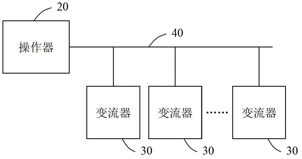
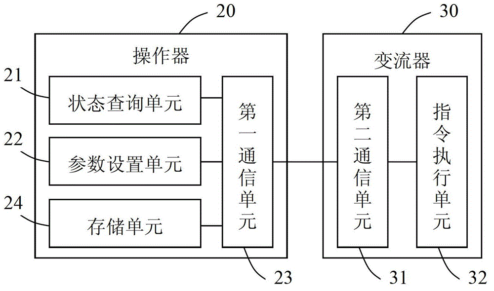
[0021] like figure 2 , 3 Shown is a schematic diagram of an embodiment of the converter debugging system of the present invention, and the system is used to realize the debugging of multiple converters in the same system. The converter debugging system in this embodiment includes an operator 20 , a debugging bus 40 and multiple converters 30 , wherein the operator 20 and the multiple converters 30 are respectively connected to the debugging bus 40 . The above operator 20 includes a state query unit 21, a parameter setting unit 22, and a first communication unit 23, and each converter 30 includes...


PUM


Abstract

The invention provides a converter debugging system which comprises a manipulator, a debugging bus and a plurality of converters, wherein the manipulator and the converters are respectively connected to the debugging bus; the manipulator comprises a state inquiring unit, a parameter setting unit and a first communication unit, wherein each converter comprises a second communication unit and a command execution unit; the state inquiry unit is used for creating an inquiry command and outputting state data returned by a corresponding converter; the parameter setting unit is used for creating a parameter setting command; the first communication unit and the second communication unit are used for achieving communication between the manipulator and the corresponding converter through a debugging bus; the command execution unit is used for generating state data according to a state inquiry command and setting parameters according to the parameter setting command. The invention further discloses a corresponding manipulator. According to the invention, the manipulator is simultaneously connected to the converters through the debugging bus, and debugging to a plurality of inverters can be achieved.

Description

technical field [0001] The invention relates to the field of converter debugging, and more specifically relates to a converter debugging system and an operator. Background technique [0002] In many power devices (such as wind power generation systems, etc.), there are often multiple converters, such as rectifiers (for converting AC to DC), inverters (for converting DC to AC), AC converters ( That is, AC frequency converter) and DC converter (that is, DC chopper), etc. And with the continuous development of industrial automation, the number and types of converters used in power equipment are increasing day by day. Each converter has many parameters that need to be debugged and monitored by the user, so as to meet the needs of different equipment. Require. [0003] like figure 1 As shown, it is the existing converter parameter debugging scheme in electric equipment, which sets a keyboard interface on each converter, and sets the parameters of the converter through the oper...

Claims


Application Information

Patent Timeline
Patent Type & Authority Applications(China)
IPC IPC(8): G01R31/00
Inventor 蒋杰郑康山
Owner SUZHOU INOVANCE TECH CO LTD
Why Eureka
Try Eureka