Direct-current voltage control unit and method for wind power generation system

A wind power generation system, DC voltage technology, applied in wind power generation, electrical components, single-grid parallel feeding arrangement, etc., can solve problems such as small interference stability of DC voltage needs to be improved, and achieve the ability to maintain fault ride-through, avoid damage, The effect of enhancing the stability of small disturbances

Active Publication Date: 2013-10-02
HUAZHONG UNIV OF SCI & TECH
5 Cites 16 Cited by

AI-Extracted Technical Summary

Problems solved by technology

But in the steady state, the small disturbance sta...

Method used

By above design, compare with the mode of carrying out control only according to the voltage signal of DC capacitor in the prior art, introduce grid frequency signal and DC voltage signal to calculate active current command signal and electromagnetic torque together in the present invention Compensation signals, and output them to the machine-side and grid-side controllers to jointly determine the control of the machine-side and grid-side converters, correspondingly, the small disturbance state of the DC voltage in the actual situation can be considered, and it can be used as a reference The factor is reflected in the control process of current and voltage, thereby effectively enhancing the small disturbanc...

Abstract

The invention discloses a direct-current voltage control unit for a wind power generation system. The direct-current voltage control unit comprises a machine-side controller, a network-side controller and a direct-current voltage controller, wherein the direct-current voltage controller is used for acquiring a direct-current voltage signal and a power grid frequency signal, calculating a corresponding active current instruction signal and a corresponding electromagnetic rotary torque compensation signal according to an acquisition signal, and outputting the active current instruction signal and the electromagnetic rotary torque compensation signal to the network-side controller and the machine-side controller respectively; the machine-side controller is used for acquiring a rotary speed signal of a power generator and a current signal of a stator of the power generator, and correspondingly adjusting a drive signal of a machine-side converter in combination with the electromagnetic rotary torque compensation signal; and the network-side controller is used for acquiring voltage and current signals, and correspondingly adjusting a drive signal of a network-side converter in combination with the active current instruction signal. The invention further discloses a corresponding direct-current voltage control method. Through the adoption of the direct-current voltage control unit and the method, the small interference stability of a direct-current voltage can be enhanced and the system fault ride-through capability can be guaranteed.

Application Domain

Technology Topic

Image

  • Direct-current voltage control unit and method for wind power generation system
  • Direct-current voltage control unit and method for wind power generation system
  • Direct-current voltage control unit and method for wind power generation system

Examples

  • Experimental program(1)

Example Embodiment

[0034] In order to make the objectives, technical solutions, and advantages of the present invention clearer, the following further describes the present invention in detail with reference to the accompanying drawings and embodiments. It should be understood that the specific embodiments described herein are only used to explain the present invention, but not to limit the present invention. In addition, the technical features involved in the various embodiments of the present invention described below can be combined with each other as long as they do not conflict with each other.
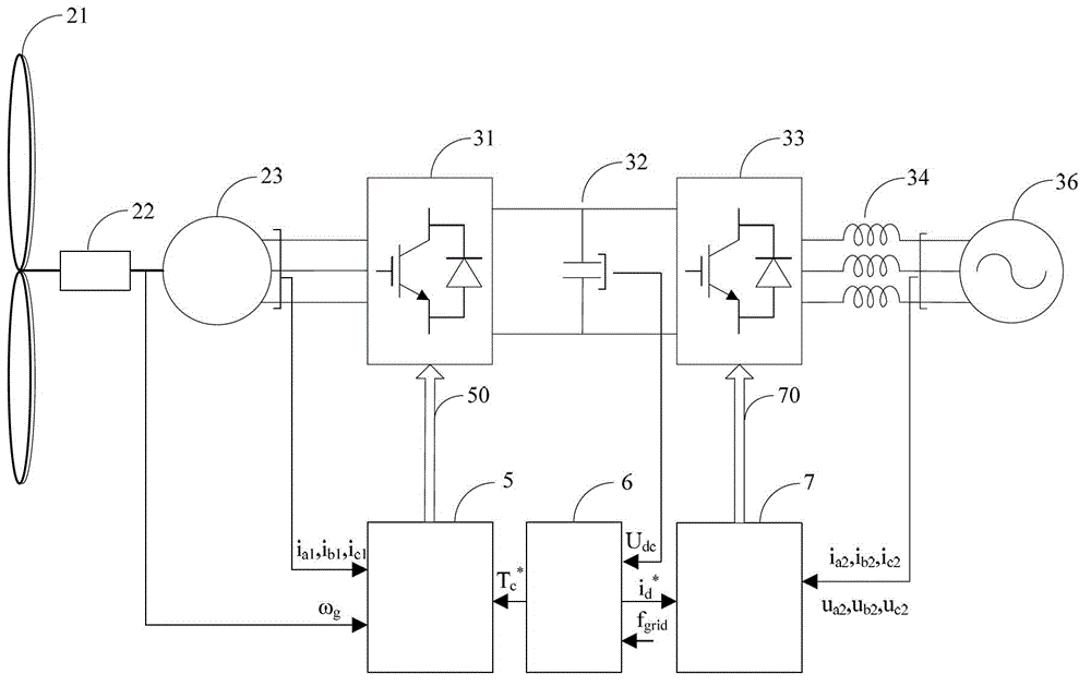
[0035] figure 1 It is a schematic diagram of the overall principle of the DC voltage control unit according to the present invention. Such as figure 1 As shown in the figure, the application object of the DC voltage control unit according to the present invention is, for example, a full-power wind power generation system. As is well known in the art, the wind power generation system includes a wind turbine 21, and power generation that converts the mechanical energy of the wind turbine 21 into electrical energy. The generator 23 (the wind turbine 21 and the generator 23 are also equipped with a gearbox 22 that performs mechanical coupling and transfers mechanical energy), a generator-side converter 31 for converting the AC voltage output by the generator 23 into a DC voltage, and the generator-side The converter 31 is electrically connected to a DC capacitor 32 for storing electric energy, and a grid-side converter 33 for converting the DC voltage of the DC capacitor 32 into an AC voltage and transmitting it to the grid 36. In addition, the wind power generation system may further include a filter 34 for performing filtering processing on the AC voltage output by the grid-side converter 33, and so on.
[0036] The DC voltage control unit constructed according to the present invention includes the machine-side controller 5 corresponding to the machine-side converter 31, the grid-side controller 7 corresponding to the grid-side converter 33, and the machine-side controller respectively. 5 The DC voltage controller 6 connected to the grid-side controller 7 in signal. Specifically, the DC voltage controller 6 is used to control the DC voltage signal U of the DC capacitor 32 dc And the frequency signal f of the grid 36 grid They are collected in real time respectively, and the corresponding active current command signal i is calculated based on these two signals d * And electromagnetic torque compensation signal T c * , Then the active current command signal i d * Output to the grid-side controller 7, and the electromagnetic torque compensation signal T c * Output to the machine-side controller 5. The machine-side controller 5 is used to collect the speed signal ω of the generator 23 in real time g And its stator three-phase current signal i a1 , I b1 , I c1 , Combined with the received electromagnetic torque compensation signal T c * , The drive signal of the machine-side converter is adjusted accordingly, that is, the switching devices in the machine-side converter are controlled accordingly, so that the speed of the generator can be controlled, so that the mechanical energy of the generator can be introduced into the DC capacitor according to the DC voltage control needs 32 in. In addition, the grid-side controller 7 is used to collect the three-phase voltage signal u of the grid in real time. a2 , U b2 , U c2 And the three-phase current signal i a2 ,,I b2 , I c2 , Combined with the received active current command signal i d * , The drive signal of the grid-side converter is adjusted accordingly, that is, the switching devices in the grid-side converter are controlled accordingly, so that the power output of the wind turbine to the grid can be controlled, and the electric energy in the DC capacitor is transmitted to the grid.
[0037] Based on the above conception, compared with the prior art that only performs control based on the voltage signal of the DC capacitor, the present invention introduces the grid frequency signal and the DC voltage signal together to calculate the active current command signal and the electromagnetic torque compensation signal, And output them to the machine-side and grid-side controllers to jointly determine the control of the machine-side and grid-side converters. Accordingly, the small disturbance state of the DC voltage in the actual situation can be considered, and it is reflected in the reference factor In the process of current and voltage control, the small disturbance stability of the DC voltage is effectively enhanced; in addition, when the grid fails, the DC voltage may increase instantaneously and even cause damage to the DC capacitor. During the process, real-time detection of the DC voltage is performed, and when the DC voltage is higher than a certain threshold, an electromagnetic torque compensation command can be generated, which can maintain the constant DC voltage, avoid the damage of the capacitor, and maintain the better fault ride-through capability of the system; , Due to the detection and subsequent calculation of the grid frequency and DC voltage signal, the output power of the wind turbine responds to the change of the grid frequency, showing a certain inertia to the grid.
[0038] According to a preferred embodiment of the present invention, such as figure 2 As shown in, the DC voltage controller 6 preferably includes a first controller 61, a second controller 62, a third controller 63, a fourth controller 64 and an adder 68, wherein the first controller 61 is used for real-time Collect the DC voltage value U of the DC capacitor 32 dc , And based on the collected value and the preset first DC voltage command value U dc1 * To calculate the first electromagnetic torque compensation command value T 1 * , And then the T 1 * As an output signal, it is output to the adder 68; the second controller 62 is used to collect the DC voltage value U of the DC capacitor 32 in real time. dc , And based on the collected value and the preset second DC voltage command value U dc2 * To calculate the second electromagnetic torque compensation command value T 2 * , And then output it to the adder 68; the third controller 63 is used to collect the DC voltage signal U of the DC capacitor 32 in real time dc And the frequency signal f of the grid grid , And based on these collected values ​​and the preset first DC voltage command value U dc1 * To calculate the third electromagnetic torque compensation command value T 3 * , And then output it to the adder 68; the adder 68 performs a summation process according to the received first, second, and third electromagnetic torque compensation command values, and then compensates the electromagnetic torque obtained after the summation process Signal T c * Output to the machine-side controller 5; in addition, the fourth controller 64 is used to collect the DC voltage signal U of the DC capacitor 32 in real time dc , And based on the collected value and the preset first DC voltage command value U dc1 * To calculate the active current command signal i d * , And then output it directly to the grid-side controller 7.
[0039] More specifically, refer to Figure 3 to Figure 6 Hereinafter, the preferred configuration of the first to fourth controllers described above will be described in further detail.
[0040] Such as image 3 As shown in, the first controller 61 preferably includes a first subtractor 611, a first PI controller 613 and a first limiter 615. The first DC voltage command value U dc1 * And real-time detected DC voltage signal U dc Input to the first subtractor 611, the DC voltage command value U dc1 * Subtract the DC voltage signal U dc The difference 612 is obtained; the difference 612 is input to the first PI controller 613 to perform the adjustment process, and the preliminary electromagnetic torque compensation command value 614 is obtained. The electromagnetic torque compensation command value 614 is input into the first limiter 615 to obtain the first electromagnetic torque compensation command value T 1 *. The highest limit value of the first limiter can be set to 1.2 times the rated electromagnetic torque of the generator 23, and the lowest limit value is -1.2 times the rated electromagnetic torque of the generator 23.
[0041] Such as Figure 4 As shown in, the second controller 62 preferably includes a second subtractor 621, a second PI controller 623, and a second limiter 625. The second DC voltage command value U dc2 * And real-time detected DC voltage signal U dc Input to the second subtractor 621, the DC voltage command value U dc2 * Subtract the DC voltage signal U dc Obtain the difference 622; input the difference 622 into the second PI controller 623 to perform the adjustment process, and obtain the preliminary electromagnetic torque compensation command value 624. Input the electromagnetic torque compensation command value 624 into the second limiter 625 to obtain the second electromagnetic torque compensation command value T 2 *. The highest limit value of the second limiter can be set to 0, and the lowest limit value is -1.2 times the rated electromagnetic torque of the generator 23. In addition, in order to realize the actual control process, it is preferable to set the second DC voltage command value U dc2 * It is set to be slightly larger than the first DC voltage command value and lower than the withstand value of the DC capacitor 32.
[0042] Such as Figure 5 As shown in, the third controller 63 preferably includes a third subtractor 631, a third PI controller 633, a third limiter 635 and a signal selector 637. The first DC voltage command value U dc1 * And real-time detected DC voltage signal U dc Input to the third subtractor, the first DC voltage command value U dc1 * Subtract the DC voltage signal U dc The difference 632 is obtained; the difference 632 is input to the third PI controller 633 to perform the adjustment process, and the preliminary electromagnetic torque compensation command value 634 is obtained. The electromagnetic torque compensation command value 634 is input into the third limiter 635 to obtain the electromagnetic torque compensation command value 636. Electromagnetic torque compensation command value 636, grid frequency f grid , "0" reference value is input into the signal selector 637, and correspondingly output different electromagnetic torque compensation command values ​​T according to the state of the grid frequency 3 * , Where when the grid frequency changes, the signal selector outputs the electromagnetic torque compensation command value 636, and when the grid frequency does not change, the signal selector outputs a reference value of "0". The highest limit value of the third limiter can be set to 1.2 times the rated electromagnetic torque of the generator 23, and the lowest limit value is -1.2 times the rated electromagnetic torque of the generator 23.
[0043] Such as Image 6 As shown in, the fourth controller 64 preferably includes a fourth subtractor 641, a fourth PI controller 643, and a fourth limiter 645. The first DC voltage command value U dc1 * And real-time detected DC voltage signal U dc Input to the fourth subtractor 641, the DC voltage command value U dc1 * Subtract the DC voltage signal U dc The difference 642 is obtained; the difference 642 is input to the fourth PI controller 643 to perform the adjustment process, and the preliminary active current reference value 644 is obtained. The active current reference value 644 is input into the fourth limiter 645 to obtain the active current command signal i to be output to the grid-side controller 7 d *. The highest limit value of the fourth limiter can be set to 1.2 times the rated current value of the grid-side converter, and the lowest limit value is -1.2 times the rated current value of the grid-side converter.
[0044] Through the above design of the specific structure of the DC voltage controller, when the system is affected by the small interference signal, the first controller 61 detects the change of the DC voltage to output an electromagnetic torque compensation command T 1 * , To the original electromagnetic torque command T 0 * Compensation is performed to prevent the change of DC voltage and dampen DC voltage oscillation. When the grid fails, the DC voltage rises above the set value U dc2 * When the second controller 62 detects the change of the DC voltage to output an electromagnetic torque compensation command T 2 * , To the original electromagnetic torque command T 0 * Compensation is performed to reduce the machine-side power injected into the DC capacitor 32 to prevent the DC voltage from rising. In addition, when the grid frequency changes, the third controller 63 detects the change in the DC voltage to output an electromagnetic torque compensation command T 3 * , To the original electromagnetic torque command T 0 * For compensation, the inertia of the fan rotor is introduced to support the grid frequency. The fourth controller 64 detects the change of the DC voltage to output the active current reference value.
[0045] Figure 7 It is a schematic diagram of the structure of a network-side controller according to a preferred embodiment of the present invention. Such as Figure 7 As shown in, the grid-side controller 7 includes a grid-side current controller 71, a grid-side drive signal generator 72 and a phase-locked loop 76. The phase locked loop 76 includes, for example, a coordinate converter 763, an integrator 761, a fifth subtractor 765, and a fifth PI controller 767. The input signal of the grid-side controller 7 is the grid three-phase voltage u a2 , U b2 , U c2 And the fan output three-phase current i a2 , I b2 , I c2 And the active current command signal i d * , The output signal is the grid-side converter drive signal 70. The input signal of the phase-locked loop 76 is the grid three-phase voltage u a2 , U b2 , U c2 , The output signal is the phase angle 762 of the grid voltage. The phase angle of the grid voltage 762 and the grid three-phase voltage u a2 , U b2 , U c2 Input to the coordinate converter 763 to obtain the q-axis grid voltage 764. The "0" reference signal and the q-axis grid voltage 764 are input to the fifth subtractor 765, and the difference 766 of the "0" reference signal minus the q-axis grid voltage 764 is obtained. The difference 766 is input into the fifth PI controller 767 to obtain the grid voltage frequency signal 768. The grid voltage frequency signal 768 is input into the integrator 761 to obtain the phase angle 762 of the grid voltage. Fan output three-phase current i a2 , I b2 , I c2 , Active current command signal i d * The phase angle 762 with the grid voltage is input to the grid-side current controller 71 to obtain a modulation signal 73. The modulation signal 73 is input to the grid-side drive signal generator 72 to obtain the grid-side converter drive signal 70.
[0046] In addition, the bandwidth of the phase-locked loop 76 can be set to be relatively small, less than 10 Hz. In this way, when the frequency of the power grid produces small signal disturbances of the electromechanical time scale, the DC voltage U dc The corresponding frequency response will be generated. When the bandwidth of the phase-locked loop 76 is close to the bandwidth of the speed loop, the speed loop can also respond to the disturbance of this frequency. In this process, the third controller 63 detects the change of the DC voltage to output an electromagnetic torque compensation command T 3 * , To the original electromagnetic torque command T 0 * Make compensation. Electromagnetic torque control is in the electromechanical time scale, by increasing or decreasing the speed to increase or decrease the mechanical energy on the rotor, thereby damping the oscillation of the corresponding frequency of the DC voltage.
[0047] Those skilled in the art can easily understand that the above descriptions are merely preferred embodiments of the present invention and are not intended to limit the present invention. The invention can be used not only in full-power wind power generation systems, but also in double-fed wind power generation systems. Any modification, equivalent replacement and improvement made within the spirit and principle of the present invention shall be included in the protection scope of the present invention.

PUM

no PUM

Description & Claims & Application Information

We can also present the details of the Description, Claims and Application information to help users get a comprehensive understanding of the technical details of the patent, such as background art, summary of invention, brief description of drawings, description of embodiments, and other original content. On the other hand, users can also determine the specific scope of protection of the technology through the list of claims; as well as understand the changes in the life cycle of the technology with the presentation of the patent timeline. Login to view more.

Similar technology patents

Method and apparatus for increasing angiogenic, growth factor in heart muscle

InactiveUS7107997B1Exposure be continuousAvoid damageDiagnosticsSurgical instrument detailsAngiogenesis FactorFactor ii
Owner:MOSES JEFFREY WARREN +3

Classification and recommendation of technical efficacy words

Why Eureka
Try Eureka