Film-forming apparatus

A film-forming device and film-forming technology, applied in lighting devices, ion implantation plating, coating, etc., can solve problems such as chamber deformation increase, waste, evaporation pattern deviation, etc.

Inactive Publication Date: 2013-10-02
CANON TOKKI CORP
View PDF6 Cites 18 Cited by
  • Summary
  • Abstract
  • Description
  • Claims
  • Application Information

AI Technical Summary

Problems solved by technology

[0006] In addition, the alignment unit for alignment protrudes in the planar direction, so there is a possibility of increasing the installation space
[0007] In addition, as the size of the substrate increases, the size of the chamber (film formation chamber) also increases, which increases the deformation of the chamber. Therefore, the deformation of the chamber acts as an overload on the internal LM (Linear Motion : linear motion) guide, shortening the life of the LM guide accordingly
In addition, if the strength of the chamber is increased to reduce deformation, the weight will increase, resulting in cost and handling problems
[0008] In addition, raw materials for vapor deposition of organic EL are very expensive, and it is desired to use vapor deposition materials efficiently without waste
That is, in a common evaporation device, after the evaporation is completed, the evaporation source will continue to eject the evaporation material until the positioning of the next substrate is completed, and this part of the amount is wasted, correspondingly making the use of the evaporation material Reduced efficiency
In addition, if the substrate is brought closer to the evaporation source, the use efficiency is improved, but there is a problem that the temperature of the substrate and the mask rises, and the evaporation pattern shifts.

Method used


Image

  • Film-forming apparatus
  • Film-forming apparatus
  • Film-forming apparatus

Examples


Embodiment

[0082] Specific embodiments of the present invention will be described based on the drawings.

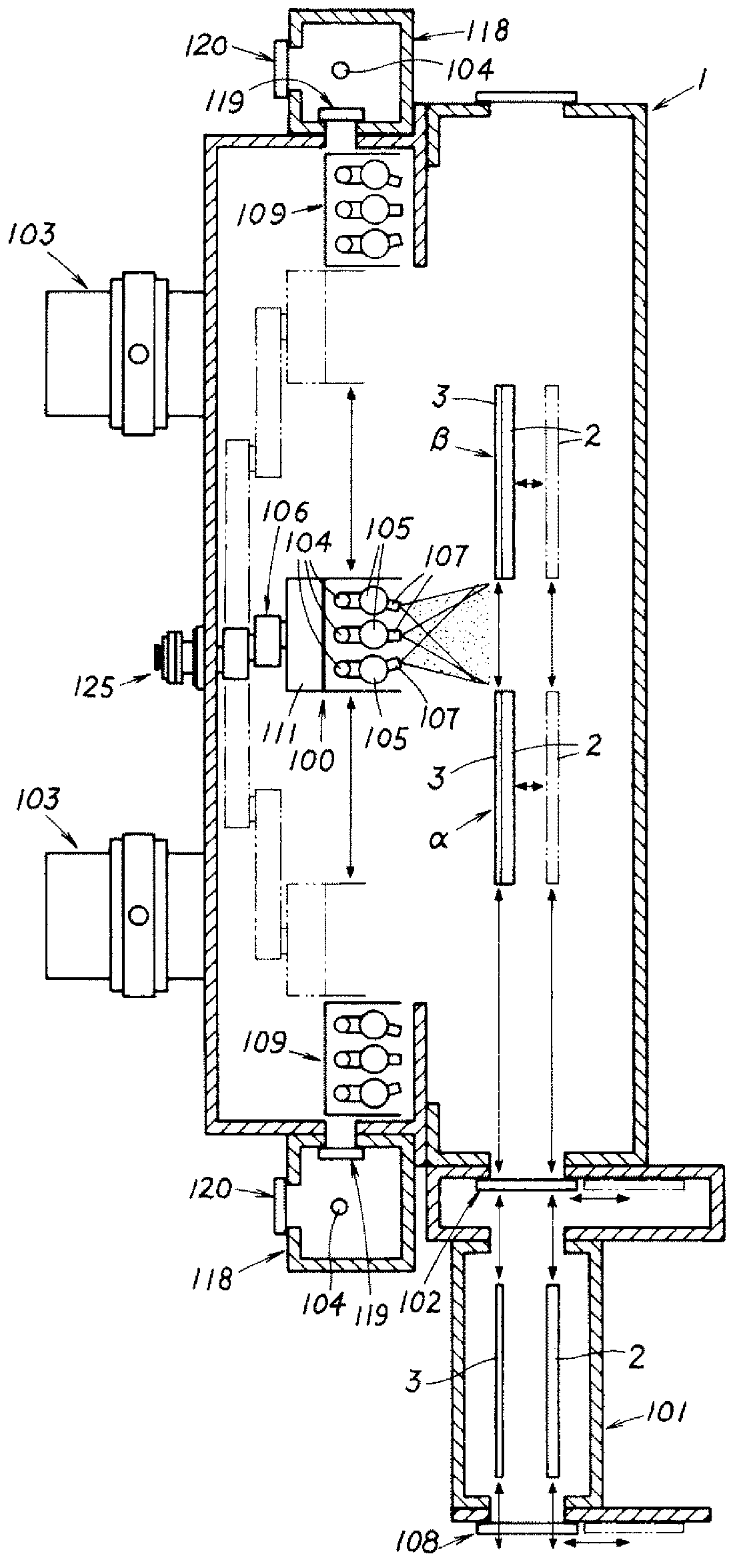
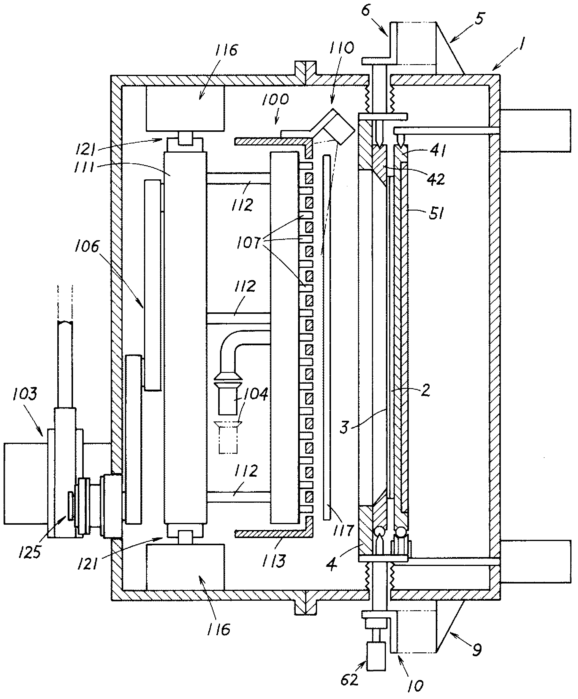
[0083] This embodiment is an embodiment in which the present invention is applied to a film-forming chamber of a film-forming apparatus (vacuum deposition apparatus) equipped with a vertically erect state conveyance (vertical conveyance chamber) that stands vertically with respect to the horizontal direction. ) Substrate transfer mechanism and mask transfer mechanism for substrate 2 and mask 3 .

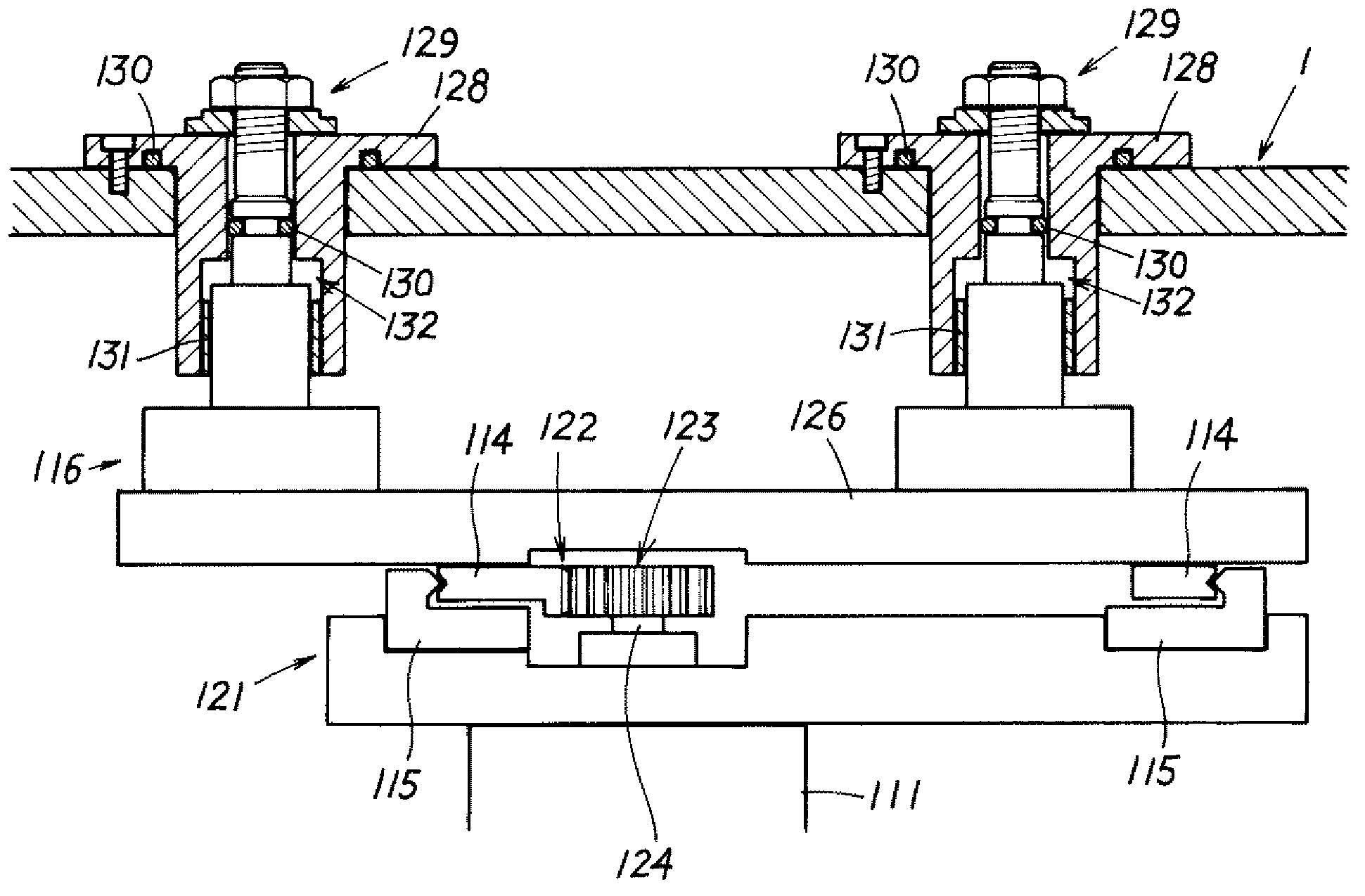
[0084] That is, the present embodiment is a film forming apparatus including a film forming chamber 1 in which a film forming material is attached to a substrate 2 held in an upright state via a mask 3 to perform For film formation, the film formation chamber 1 is provided with: an alignment driving mechanism, which makes the alignment frame 4 which installs the mask 3 in an upright state move relative to the substrate 2 to adjust and move the mask 3 Alignment with the substrate 2, so tha...


PUM


Abstract

Provided is a film-forming apparatus, which is extremely useful, and which can be applied even to large substrates of the fourth and higher-order generations. The film-forming apparatus is provided with a film-forming chamber (1), in which a film is formed on a substrate (2) by adhering a film-forming material through a mask (3), said substrate being held in an upright state. The film-forming chamber (1) is provided with: an alignment drive mechanism, which aligns the mask (3) and the substrate (2) with each other, such that the mask (3) is at a correct position with respect to the substrate (2); an evaporation source (100), which can move in the transfer direction of the substrate (2) or the mask (3); and a mask transfer mechanism and a substrate transfer mechanism, which respectively transfer the substrate (2) and the mask (3) in the upright state to each of a plurality of film-forming positions facing the evaporation source (100). The film-forming apparatus is configured such that the mask (3) and the substrate (2) are aligned with each other at one film-forming position by means of the alignment drive mechanism, while performing film formation at other film-forming position by means of the evaporation source (100).

Description

technical field [0001] The present invention relates to a film forming device. Background technique [0002] Currently, regarding the transport method of organic EL (electro-luminescence: electroluminescence) display panels in the manufacturing equipment, since the size of the substrate is, for example, the half-cut size of the fourth generation, the deflection of the glass substrate due to gravity is small, and it is not feasible. The problem, therefore, is that face-down horizontal conveyance becomes mainstream. [0003] However, it is clear that the size of the substrate will increase in the future (4th generation or higher), and in the case of horizontally transferring the substrate, the installation space of the device will increase as the substrate becomes larger. [0004] In addition, even if the size of the substrate becomes larger, the accuracy of calibration remains unchanged, which leads to relatively increased difficulty in alignment. Furthermore, there is a co...

Claims


Application Information

Patent Timeline
Patent Type & Authority Applications(China)
IPC IPC(8): C23C14/04C23C14/24H01L51/50H05B33/10
CPCC23C14/042C23C14/24C23C14/56
Inventor 田岛三之内田敬自藤塚正直高桥悌二
Owner CANON TOKKI CORP
Why Eureka
Try Eureka