
A sliding form system variable diameter assembled sliding form platform

A prefabricated, sliding-form technology, applied in the direction of formwork/template/work frame, large-capacity bulk material storage, on-site preparation of building components, etc. problems such as the length of small radiating beams, to achieve the effect of improving the reuse rate, reducing the construction cost and reasonable structural design

Active Publication Date: 2015-11-04
CHINA NAT CHEM ENG THIRD CONSTR
View PDF6 Cites 0 Cited by
  • Summary
  • Abstract
  • Description
  • Claims
  • Application Information

AI Technical Summary

Problems solved by technology

[0007] The purpose of the present invention is to overcome the shortcomings of the fixed size of the radiation beam of the sliding form platform in the prior art, and it is inconvenient to adjust the size of the sliding form platform according to actual needs, and provides a sliding form system variable diameter assembled sliding form platform, which adopts the present invention The technical solution can achieve the purpose of increasing or reducing the length of the radiation beam (ie: increasing or reducing the diameter of the sliding form platform) by replacing the variable-diameter radiation beam truss assembly

Method used


Image

  • A sliding form system variable diameter assembled sliding form platform
  • A sliding form system variable diameter assembled sliding form platform
  • A sliding form system variable diameter assembled sliding form platform

Examples


Embodiment 1

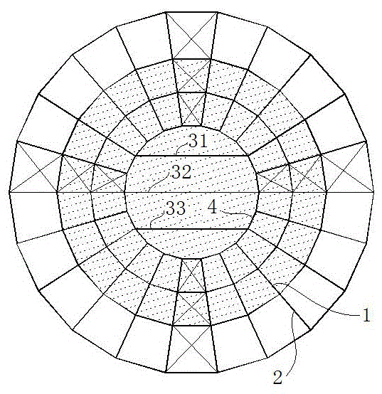
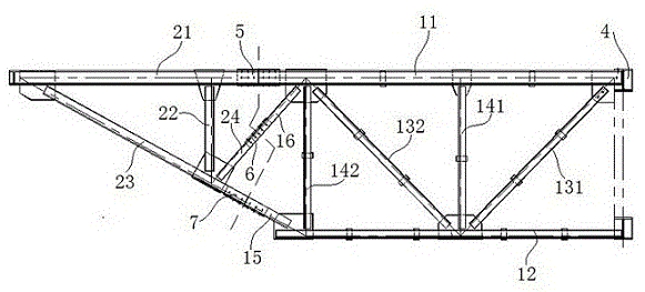
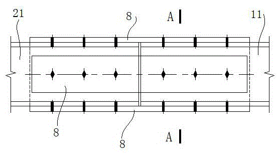
[0028] to combine figure 1 with figure 2 , a variable-diameter assembled sliding-form platform of a sliding form system in this embodiment includes a central steel ring assembly, a fixed-diameter radiant beam truss assembly 1 and a variable-diameter radiant beam truss assembly 2 . Such as figure 1As shown, the central steel ring assembly in this embodiment includes a first shaped steel beam 31, a second shaped steel beam 32, a third shaped steel beam 33 and a central steel ring truss 4, the central steel ring truss 4 is a circular structure, The center steel ring truss 4 is internally provided with a first steel beam 31, a second steel beam 32 and a third steel beam 33, and the first steel beam 31 and the third steel beam 33 are located on both sides of the second steel beam 32, And respectively set parallel to the second steel beam 32, the second steel beam 32 is located at the diameter position of the central steel ring truss 4, the first steel beam 31 and the third ste...


PUM


Abstract

The invention discloses a variable-diameter assembly type sliding-mold platform of a sliding-mold system and belongs to the technical field of sliding-mode engineering. The variable-diameter assembly type sliding-mold platform comprises a central steel ring assembly, fixed-diameter radial-beam truss assemblies and variable-diameter radial-beam truss assemblies, wherein each fixed-diameter radial-beam truss assembly comprises a fixed-diameter upper chord, a lower chord, a first diagonal web member, a second diagonal web member, a first vertical rod, a second vertical rod, an end-part diagonal web connecting rod and a diagonal web connecting rod; the fixed-diameter upper chords and the lower chords are arranged in parallel from top to bottom; the right ends of the fixed-diameter upper chords and the lower chords are respectively connected to the peripheral edge of a central steel-ring truss; the fixed-diameter radial-beam truss assemblies at the periphery of the central steel-ring truss are in radial distribution; each variable-diameter radial-beam truss assembly comprises a variable-diameter upper chord, a variable-diameter vertical rod, a variable-diameter end-part diagonal web member and a variable-diameter diagonal web member; and the variable-diameter radial-beam truss assemblies are connected to the outer sides of the fixed-diameter radial-beam truss assemblies. The variable-diameter assembly type sliding-mold platform disclosed by the invention has the advantage that by replacement of the variable-diameter radial-beam truss assemblies, the effect of increasing or decreasing the diameter of the sliding-mode platform can be achieved.

Description

technical field [0001] The invention relates to the technical field of sliding form engineering auxiliary devices, and more specifically, relates to a variable diameter assembled sliding form platform of a sliding form system. Background technique [0002] Sliding form engineering technology is a kind of construction with high degree of mechanization, fast construction speed, less site occupation, strong structural integrity, good seismic performance, safe operation guarantee, and remarkable comprehensive environmental and economic benefits in the construction of cast-in-place concrete structures in my country. technique, often referred to simply as "slip mode". [0003] However, the sliding form includes not only ordinary formwork or special formwork and other tool formwork, but also comprehensive technologies such as power sliding equipment and supporting construction technology. At present, hydraulic jacks are mainly used as the driving force for sliding. The tool-type fo...

Claims


Application Information

Patent Timeline
Patent Type & Authority Patents(China)
IPC IPC(8): E04G11/22E04H7/26
Inventor 苏鹏候钢领夏节文李文蔚曹春红刘建卫杨步前
Owner CHINA NAT CHEM ENG THIRD CONSTR
Learn More