Annular workbench for split charging of pistons and connecting rods of engine

A technology of piston connecting rod and engine, applied in the direction of workbench, manufacturing tools, etc., can solve the problems of low degree of automation, large floor space, high labor intensity of workers, etc., and achieve the effect of saving investment and small floor space

Active Publication Date: 2013-05-15
ANHUI JIANGHUAI AUTOMOBILE GRP CORP LTD
View PDF9 Cites 0 Cited by
  • Summary
  • Abstract
  • Description
  • Claims
  • Application Information

AI Technical Summary

Problems solved by technology

The original manual sub-packaging station consists of several separate operating stations, which require operators to manually transfer between the stations. The degree of automation is low, and the labor intensity of workers is high. It is mostly used in production lines with small production capacity.
For a production line with more than 100,000 units per year, square automatic roller conveyor lines are mostly used for the subassembly of pistons and connecting rods. Four automatic turntables are required for transfer at the interface of the rollers. The equipment investment cost is high and the floor area is large.

Method used


Image

  • Annular workbench for split charging of pistons and connecting rods of engine
  • Annular workbench for split charging of pistons and connecting rods of engine
  • Annular workbench for split charging of pistons and connecting rods of engine

Examples


Embodiment

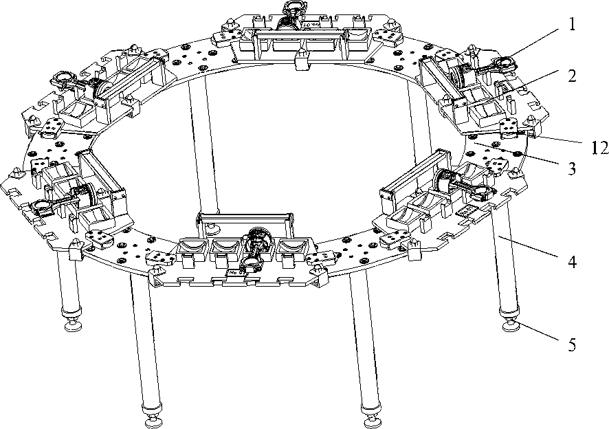
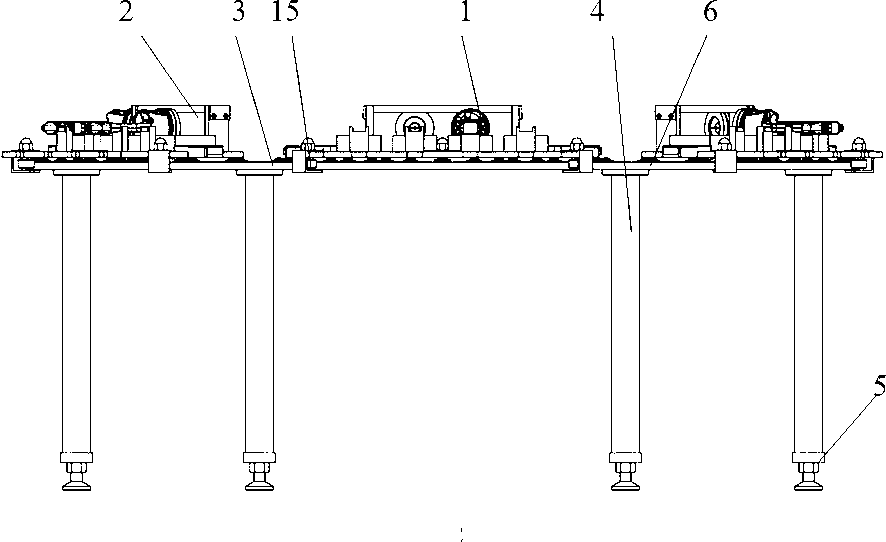
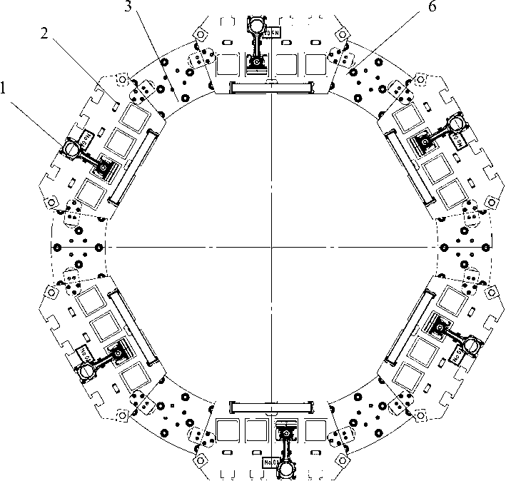
[0025] see figure 1 , figure 2 and image 3 , the annular workbench used for engine piston and connecting rod subassembly includes an annular turntable 3, and the effect of the annular turntable 3 is equivalent to a ring-shaped conveying guide rail. Universal balls 6 are evenly distributed on the turntable 3, and the turntable 3. Six struts 4 are fixedly installed on the bottom surface, and an anchor 5 is fixedly installed at the lower end of each strut 4. On the turntable 3, there are six piston connecting rod sub-packaging tray mechanisms 2, see Figure 4 and Figure 5 , through the universal ball 6 to make the piston connecting rod packing tray mechanism 2 slide and transport on the turntable 3 conveniently. Piston connecting rod packing tray mechanism 2 comprises tray base plate 7, four piston support blocks 9 are evenly distributed side by side on the tray base plate 7, piston support blocks 9 are box-shaped, and the bottom surface is a concave arc surface; The two ...


PUM


Abstract

The invention relates to an annular workbench for split charging of pistons and connecting rods of an engine. The workbench comprises a turnover table and more than five piston and connecting rod split charging tray mechanisms. The turnover table is an annular conveying guide rail with a hole at the middle, the lower part of the turnover table is connected with a stay bar through a bolt, and a universal ball is mounted on the tabletop for facilitating the support of trays for circulating conveying. Piston support blocks and connecting rod support blocks, which are made of nylon materials, aremounted on baseplates of the piston and connecting rod split charging tray mechanisms through screws, a connecting rod cover material box is arranged at the top of a handle of each piston and connecting rod split charging tray mechanism, and the trays have the functions of placing the pistons, the connecting rods and connecting rod covers and assembling a piston and connecting rod assembly. The workbench provided by the invention is small in floor area, the power-free manual pushing, pulling and conveying way can be adopted among working positions, an automatic revolution mechanism between a power roller way and a roller way is not required, and the investment is effectively saved. Simultaneously, the diameter of the annular workbench can be increased or decreased according to the productivity, the working positions of different numbers can be set, and the limitations on the productivity are eliminated.

Description

technical field [0001] The invention relates to an engine piston and connecting rod disassembly method and disassembly equipment, in particular to an annular end-to-end disassembly table. Background technique [0002] At present, when the assembly line of an automobile engine is assembling pistons and connecting rods in cylinder bores, an independent piston and connecting rod subassembly line or a manual subassembly station is usually set up outside the main line body according to different production capacity. Piston and connecting rod sub-assembly is divided into multiple stations such as piston ring installation, connecting rod disassembly, piston pin press-fitting, and connecting rod shoe selection. The original manual sub-packaging station consists of several separate operating stations, which require operators to manually transfer between stations. The degree of automation is low, and the labor intensity of workers is high. It is mostly used in production lines with sm...

Claims


Application Information

Patent Timeline
Patent Type & Authority Patents(China)
IPC IPC(8): B25H1/02
Inventor 黄浩赵贺金曹金贵
Owner ANHUI JIANGHUAI AUTOMOBILE GRP CORP LTD
Why Eureka
Try Eureka