Electrostatically driving electrostatic detection bulk acoustic wave resonance three-axis microgyroscope and manufacturing method thereof

An electrostatic detection and electrostatic drive technology, applied in the field of micro gyroscopes, can solve problems such as increased processing complexity, low signal sensitivity, and device performance impact, and achieve high yield, simple manufacturing process, and good symmetry

Active Publication Date: 2013-10-09
SHANGHAI JIAO TONG UNIV
View PDF9 Cites 9 Cited by
  • Summary
  • Abstract
  • Description
  • Claims
  • Application Information

AI Technical Summary

Problems solved by technology

[0004] This technology has the following disadvantages: the gyroscope adopts the traditional spring-mass structure model, the signal sensitivity obtained is not high, the Q value is low, the zero drift is too large, and the impact resistance is poor; in addition, in the process of applying electrostatic force In the process, it is necessary to apply a ground voltage to the mass block. This contact will undoubtedly have a certain impact on the performance of the device, and will undoubtedly greatly increase the processing complexity.

Method used


Image

  • Electrostatically driving electrostatic detection bulk acoustic wave resonance three-axis microgyroscope and manufacturing method thereof
  • Electrostatically driving electrostatic detection bulk acoustic wave resonance three-axis microgyroscope and manufacturing method thereof
  • Electrostatically driving electrostatic detection bulk acoustic wave resonance three-axis microgyroscope and manufacturing method thereof

Examples


Embodiment Construction

[0031] The present invention will be described in detail below in conjunction with specific embodiments. The following examples will help those skilled in the art to further understand the present invention, but do not limit the present invention in any form. It should be noted that those skilled in the art can make several modifications and improvements without departing from the concept of the present invention. These all belong to the protection scope of the present invention.

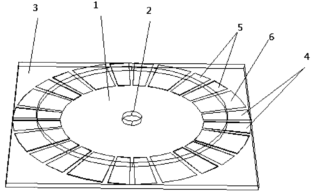
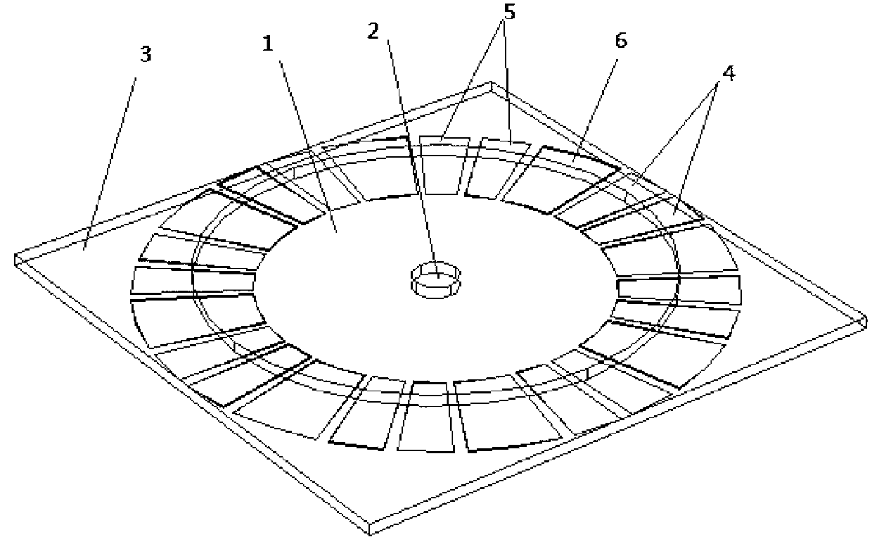
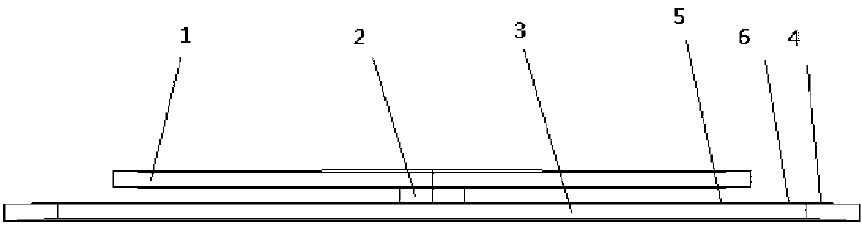
[0032] like figure 1 , figure 2 , image 3 As shown, this embodiment provides an electrostatically driven electrostatic detection body acoustic resonant three-axis micro-gyroscope, including:

[0033] A disc vibrator 1 without a release hole;

[0034] A cylindrical support column 2 located in the center of the disk vibrator 1;

[0035] a substrate 3;

[0036] And the drive electrode 4, the detection electrode 5 and the common electrode 6 arranged on the substrate 3 parallel to the disk vibra...


PUM


Abstract

The invention relates to an electrostatically driving electrostatic detection bulk acoustic wave resonance three-axis microgyroscope and a manufacturing method thereof. The gyroscope comprises a disk vibrator with no release hole, a substrate, a cylindrical supporting pillar, driving electrodes, detection electrodes and common electrodes, wherein the disk vibrator is fixed on the substrate through the supporting pillar; the disk vibrator is vertical to an z-axis of the substrate; the driving electrodes, the detection electrodes and the common electrodes are disposed on the substrate in a circumference manner and parallel to the disk vibrator and have a gap with the disk vibrator; and every common electrode is disposed between two driving electrodes and two detection electrodes. The gyroscope is manufactured by an MEMS processing technology which is simple in manufacturing process, high in reliability and can guarantee relatively low cost and relatively high yield. A non-contact electrode structure is employed by the gyroscope and has smaller influence on the vibration of resonators. Besides, the gyroscope is small in size, simple in structure and easily achievable in manufacturing process, and is suitable for large-scale production.

Description

technical field [0001] The invention relates to a micro-gyroscope in the field of micro-electromechanical technology, in particular to an electrostatically driven electrostatic detection body acoustic wave resonant three-axis micro-gyroscope and a preparation method thereof. Background technique [0002] Gyroscope is an inertial device that can be sensitive to the angle or angular velocity of the carrier, and it plays a very important role in the fields of attitude control, navigation and positioning. With the development of national defense technology and aviation and aerospace industries, the requirements of inertial navigation systems for gyroscopes are also developing in the direction of low cost, small size, high precision, high reliability, and adaptability to various harsh environments. [0003] After searching the literature of the existing technology, it is found that the Chinese patent "Dual-axis MEMS Gyroscope", patent application number: 201020033300.7, uses MEMS...

Claims


Application Information

Patent Timeline
IPC IPC(8): G01C19/5698
Inventor 张卫平成宇翔许仲兴唐健张弓陈文元汪濙海
Owner SHANGHAI JIAO TONG UNIV
Why Eureka
Try Eureka