
Method for reporting channel quality indication

A channel quality indication and quality indication technology, applied in wireless communication, digital transmission system, electrical components, etc., can solve downlink loss, base station cannot reduce modulation and coding mode in time, link capacity is not fully utilized, etc. problem, to achieve the effect of improving link performance

Active Publication Date: 2013-10-09
CHANGZHOU OUJIA COMM EQUIP
View PDF4 Cites 2 Cited by
  • Summary
  • Abstract
  • Description
  • Claims
  • Application Information

AI Technical Summary

Problems solved by technology

[0008] The existing technology does not give a definition for how to select which CQIs to report first in the multi-carrier situation. If the randomly discarded CQI happens to be much lower than the previous CQI, then the base station will not be able to reduce the modulation and coding method in time, and the downlink has Link loss may occur because of this; on the contrary, if the discarded CQI happens to be much higher than the previous CQI, then the base station fails to make full use of the improved link quality, chooses a better modulation and coding method, and the link capacity is not fully utilized

Method used


Image

  • Method for reporting channel quality indication
  • Method for reporting channel quality indication
  • Method for reporting channel quality indication

Examples


Embodiment 1

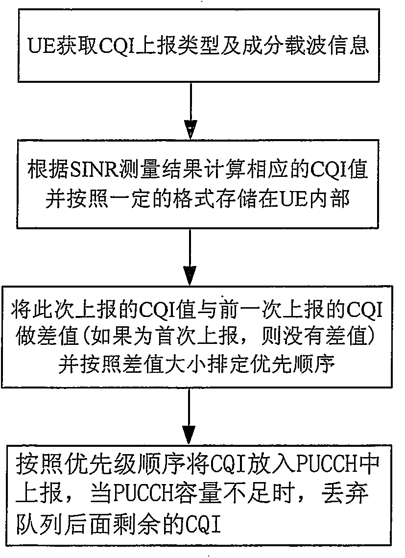
[0030] In this embodiment, the wireless terminal (UE) is configured with 5 carriers, denoted as CC1, CC2, CC3, CC4, and CC5 respectively. Such as figure 1 It is a schematic flow diagram of the method of the first embodiment of the present invention, including:

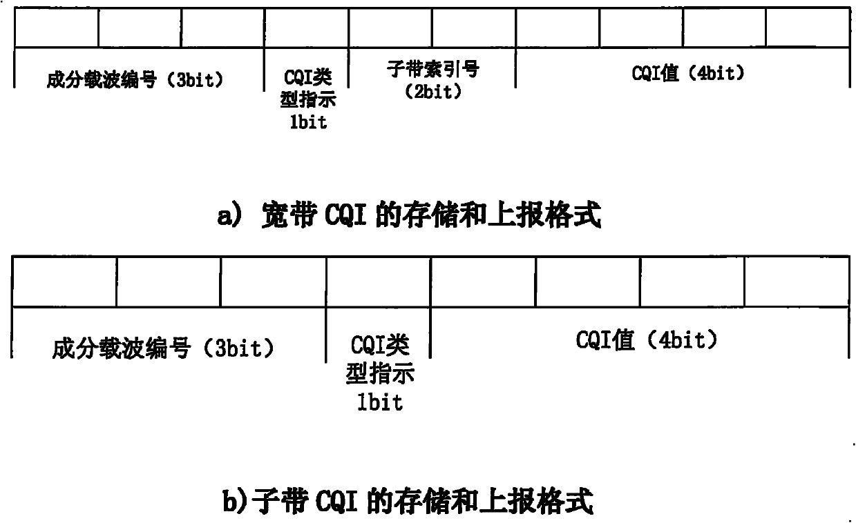
[0031] Step S101: The UE obtains from the base station the component carriers CC1, CC2, CC3, CC4, and CC5 that need to measure CQI and how to report the above-mentioned component carriers, specifically including the way of reporting the wideband CQI or the way of reporting the sub-band CQI; for reporting the sub-band CQI mode, the index of the subband is also included.

[0032] The so-called wideband CQI refers to the average CQI value of the component carrier on the entire bandwidth; the sub-band CQI refers to the CQI value of the component carrier on a certain part of the bandwidth.

[0033] Preferably, the way for the base station to inform the UE to report the CQI is usually to send it to the UE in layer 3 inform...

Embodiment 2

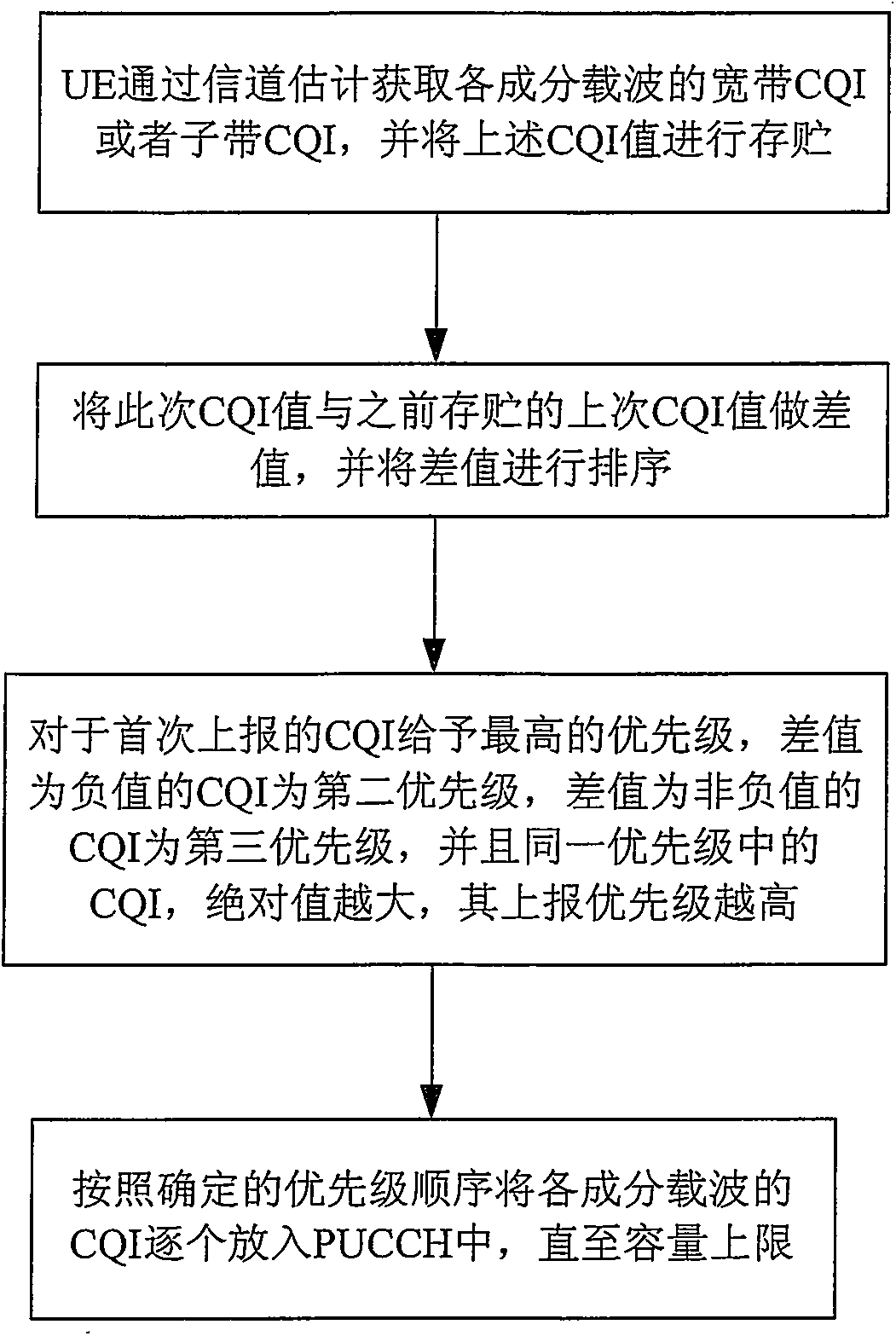
[0070] For the scenario where there are both negative and non-negative values ​​in the CQI difference, the implementation process is as follows image 3 shown. Assume that the UE is configured with 5 carriers, namely CC1, CC2, CC3, CC4, and CC5. Using the method of embodiment 1, the difference information between this CQI and the previous CQI has been obtained, as shown in Table 3:

[0071] table 3

[0072]

[0073]

[0074] Compared with Embodiment 1, Embodiment 2 has two more steps when scheduling CQI reporting priority, namely

[0075] Step S1041, setting the priority of the negative CQI difference to be higher than the priority of the non-negative CQI difference; and

[0076] Step S1042, sorting the CQI difference values ​​to non-negative values, and the higher the absolute value, the higher the priority.

[0077] Specifically, as shown in Table 3, the CQI of CC3 is reported for the first time, so it has the highest priority. Among the remaining CQIs, the CQI dif...


PUM


Abstract

The invention discloses a method for reporting a channel quality indication by a wireless terminal in an LTE (long term evolution) multi-carrier system. In the method disclosed by the invention, the wireless terminal calculates a difference value between the channel quality indication (CQI) value of this time and the CQI of the last time according to channel estimation, and determines the reporting priority of each component carrier according to the difference value, and if the CQI is reported for the first time, then the priority is the highest; for the CQI which is not reported for the first time, the priorities of the negative CQI difference values are set to be higher than the priorities of the non-negative CQI difference values; then the CQI value of each component carrier is reported one by one according to a determined priority sequence until the upper limit of an unlink control channel capacity is achieved. According to the method provided by the invention, preferential transmission for a channel quality indication with high influence on wireless communication can be ensured in a scene with a limited unlink control channel capacity, so that on one hand, the normal communication of all wireless links is kept; on the other hand, a link capacity is increased as far as possible.

Description

technical field [0001] The present invention relates to the technical field of wireless communication, in particular to a method for a wireless terminal to report a channel quality indicator (CQI) of a component carrier in an LTE multi-carrier system. Background technique [0002] Long-Term Evolution (LTE) is the evolution of the third-generation mobile communication system. During the standardization process of LTE, various new enhancement technologies have been added to provide better performance. For example, in order to improve spectrum efficiency and data rate, LTE has changed from Starting from R-10, the carrier aggregation technology is introduced. The carrier aggregation technology can aggregate multiple component carriers together to form a larger system bandwidth, thereby increasing the data transmission rate. In LTE systems of R-10 and later versions, a terminal supporting carrier aggregation can work in a single-carrier scenario, that is, there is only one prima...

Claims


Application Information

Patent Timeline
Patent Type & Authority Applications(China)
IPC IPC(8): H04L1/00H04W24/10
Inventor 李文龙
Owner CHANGZHOU OUJIA COMM EQUIP
Learn More