
Granary monitoring method, device, equipment and system based on radar offset imaging

A technology of offset imaging and monitoring equipment, which is applied in the field of information and communication, can solve the problems of not paying attention to grain electrical parameters, high stability requirements, etc., and achieve the effect of eliminating data dependence, reducing reliability and stability dependence, and accurate monitoring

Active Publication Date: 2020-06-02
厦门精益远达智能科技有限公司
View PDF13 Cites 1 Cited by
  • Summary
  • Abstract
  • Description
  • Claims
  • Application Information

AI Technical Summary

Problems solved by technology

However, monitoring the moisture content of grain through the principle of ground penetrating radar can more accurately explain the quality change of grain, but it does not pay attention to the relationship between grain electrical parameters and other factors. Radar movement conducts segmented grain monitoring, which has high requirements for the accuracy of device installation and the stability of system operation

Method used


Image

  • Granary monitoring method, device, equipment and system based on radar offset imaging
  • Granary monitoring method, device, equipment and system based on radar offset imaging
  • Granary monitoring method, device, equipment and system based on radar offset imaging

Examples


no. 1 example

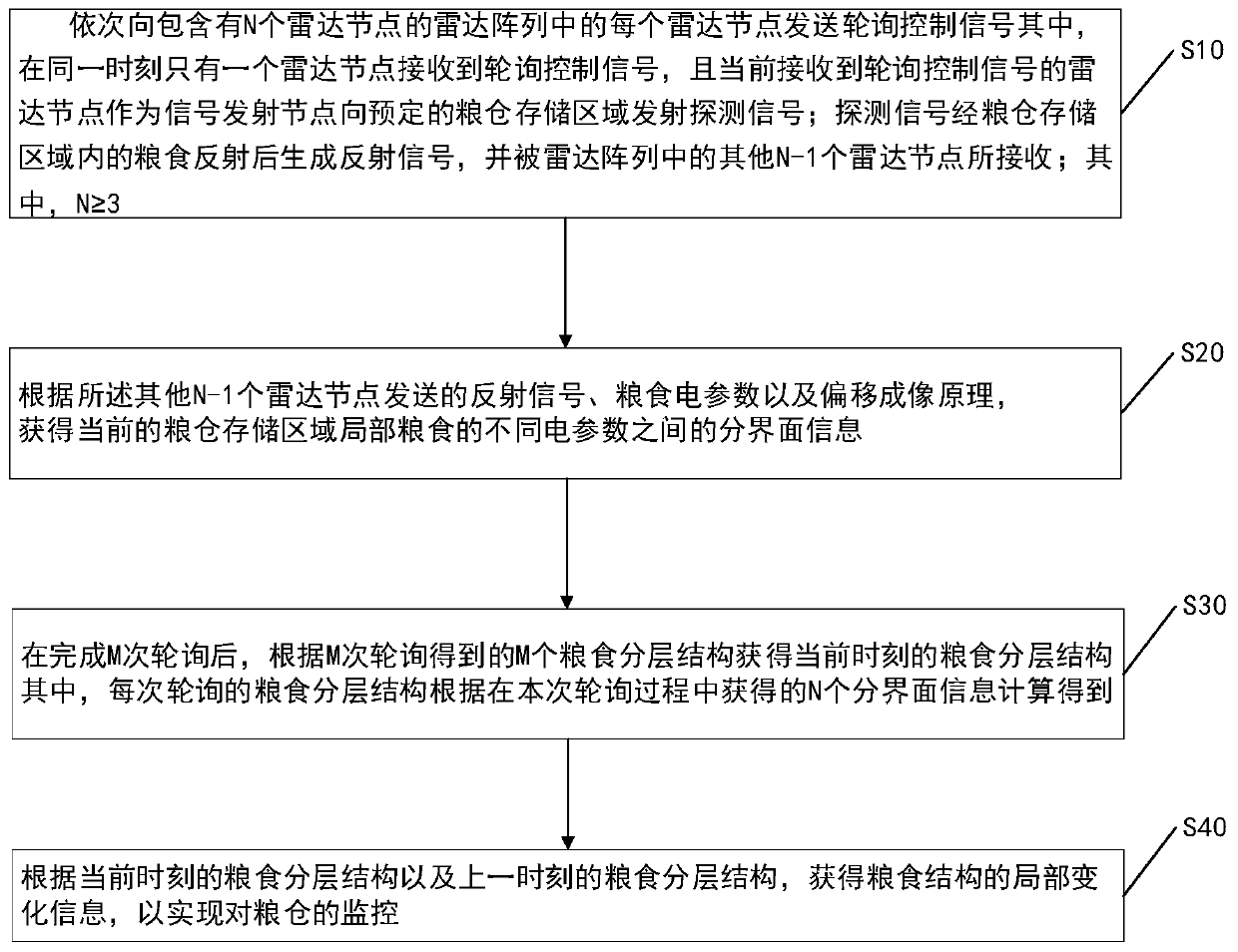
[0046] see figure 1 , the present invention provides a granary monitoring method based on radar offset imaging, specifically comprising the following steps:

[0047] S10, sending a polling control signal to each radar node in the radar array containing N radar nodes in turn; wherein, only one radar node receives the polling control signal at the same time, and currently receives the polling control signal The radar node of the signal is used as a signal transmitting node to transmit a detection signal to the predetermined granary storage area; the detection signal generates a reflected signal after being reflected by the grain in the granary storage area, and is detected by other N-1 radar nodes in the radar array Received.

[0048] In this embodiment, the radar array is composed of N frequency-modulated continuous-wave millimeter-wave radars, and the N frequency-modulated continuous-wave millimeter-wave radars are installed directly above the granary storage area, and accord...

no. 2 example

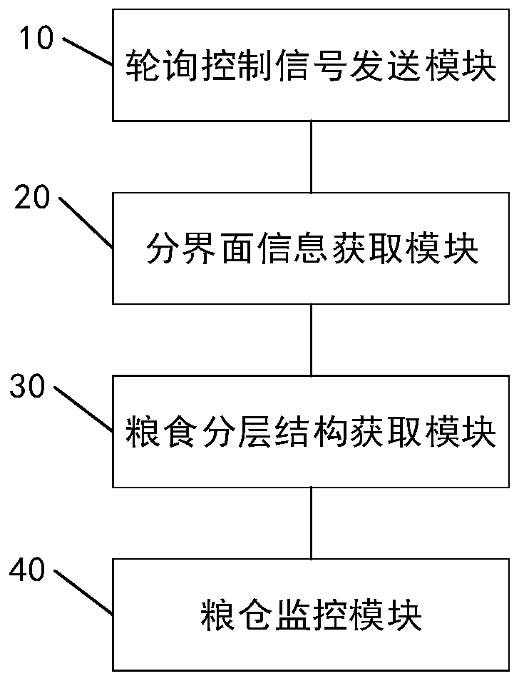
[0065] see figure 2 , the second embodiment of the present invention provides a granary monitoring device based on radar offset imaging, including:

[0066] The polling control signal sending module 10 is used to send the polling control signal to each radar node in the radar array containing N radar nodes in turn; wherein, only one radar node receives the polling control signal at the same time, and The radar node currently receiving the polling control signal is used as a signal transmitting node to transmit a detection signal to a predetermined granary storage area; the detection signal generates a reflected signal after being reflected by the grain in the granary storage area, and is detected by the radar array Received by the other N-1 radar nodes.

[0067] The interface information acquisition module 20 is used to obtain the distribution of different electrical parameters of the local grain in the current granary storage area according to the reflected signals sent by ...

no. 3 example

[0074] The present invention provides a granary monitoring device based on radar offset imaging, comprising a processor, a memory, and a computer program stored in the memory and configured to be executed by the processing, when the processor executes the computer program, the The granary monitoring method based on radar offset imaging as described in any of the above embodiments.


PUM


Abstract

The invention provides a radar migration imaging based granary monitoring method, device, equipment and system. The method includes the following steps: successively sending a polling control signal to each radar node in a radar array containing N radar nodes, wherein only one radar node receives the polling control signal at the same time, the radar node currently receiving the polling control signal is a signal emission node to emit a detection signal to granary storage areas so as to generate reflected signals, and other N-1 radar nodes receive the reflected signals; obtaining interface information between different electrical parameters of local grain the current granary storage area according to the reflected signals, grain electrical parameters and migration imaging principles of theother N-1 radar nodes; obtaining a grain layered structure at that moment according to M grain layered structures obtained by M rounds of polling after the M rounds of polling are finished; and obtaining the local change information of grain structures according to the grain layered structure at that moment and the grain layered structure at last moment so that the monitoring of granaries can berealized.

Description

technical field [0001] The invention relates to the field of information communication technology, in particular to a granary monitoring method, device, equipment and system based on radar offset imaging. Background technique [0002] Food is the basic demand of the national economy and the people's livelihood, and its supply and demand balance, market stability and other factors directly affect the security, stability and development of the country. Therefore, how to ensure the long-term safe storage of grain has become a major event of national concern. For the storage of grain, it is not only necessary to control the natural environmental conditions such as the temperature and humidity of the storage granary, but also the supervision and monitoring of the granary is also a focus and difficulty that needs to be paid attention to. Due to the large amount of grain stored in the granary, which contains huge economic benefits, various violations of laws and regulations, such ...

Claims


Application Information

Patent Timeline
Patent Type & Authority Patents(China)
IPC IPC(8): G01S13/88G01S13/89
CPCG01S13/88G01S13/89
Inventor 张谅赵铁刚
Owner 厦门精益远达智能科技有限公司
Learn More