
A chemical reaction filter device for easy extraction of gas

A chemical reaction and filtering device technology, applied in the field of chemical machinery, can solve the problems that the reaction tank cannot be disassembled and cleaned and ensure the sealing performance of the reaction at the same time, it is inconvenient to control the amount of reaction liquid added, and it is inconvenient for particle recovery operations. Adding solid particles, easy to disassemble and separate, easy to disassemble and clean

Active Publication Date: 2021-07-27
山东沾化天元精细化工有限公司
View PDF22 Cites 0 Cited by
  • Summary
  • Abstract
  • Description
  • Claims
  • Application Information

AI Technical Summary

Problems solved by technology

[0004] The purpose of the present invention is to provide a kind of chemical reaction filter device that is convenient for extracting gas, to solve the inconvenient control of the addition amount of reaction solution proposed in the above-mentioned background technology, only one group of reaction devices is provided, it is impossible to carry out comparative tests, and it needs to be separated, etc. Add the reaction liquid in a certain amount; it is inconvenient to add solid particles, and the problem of convenient disassembly and cleaning and ensuring the sealing of the reaction tank cannot be satisfied at the same time, and there is no gas recovery device; the device for filtering and separating the reactants is too simple, and the filtering effect is poor , the degree of filtration is not high; there is no heating and precipitation device for the reaction particles, so it is inconvenient to recover the particles on the filter screen

Method used


Image

  • A chemical reaction filter device for easy extraction of gas
  • A chemical reaction filter device for easy extraction of gas
  • A chemical reaction filter device for easy extraction of gas

Examples


Embodiment Construction

[0029] The following will clearly and completely describe the technical solutions in the embodiments of the present invention with reference to the accompanying drawings in the embodiments of the present invention. Obviously, the described embodiments are only some, not all, embodiments of the present invention. Based on the embodiments of the present invention, all other embodiments obtained by persons of ordinary skill in the art without making creative efforts belong to the protection scope of the present invention.

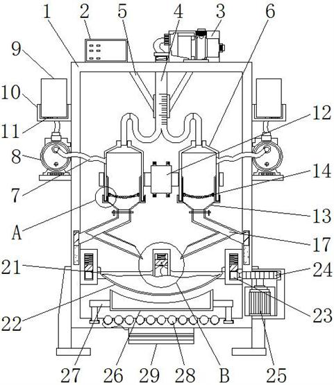
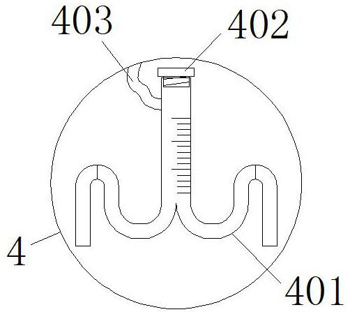
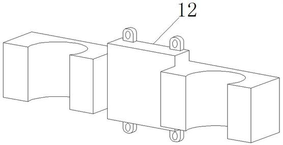
[0030] see Figure 1-8, the present invention provides a technical solution: a chemical reaction filter device that is convenient for extracting gas, including a kettle body 1, a control panel 2, a booster pump 3, a liquid injection device 4, a fixing frame 5, a first reaction cylinder 6, a pumping Suction pipe 7, vacuum pump 8, gas collector 9, installation block 10, pressure sensor 11, fixed block 12, second reaction cylinder 13, sieve plate 14, jacket block...


PUM


Abstract

The invention discloses a chemical reaction filter device for easy extraction of gas, which comprises a kettle body, a pressure sensor and a heater. A control panel is installed on the left side of the upper end of the kettle body, and a liquid injection is connected to the lower end of the booster pump. device, the left and right sides of the lower end of the liquid injection device are connected with the first reaction cylinder, the end of the suction pipe far away from the first reaction cylinder is connected with a vacuum pump through the kettle body, and the outer side of the gas collection cylinder is connected with a mounting block, the pressure sensor is disposed between the lower surface of the gas collector and the installation block, and the middle and outer sides of the first reaction cylinder are snap-connected with a fixed block. This chemical reaction filter device that is convenient for extracting gas can be used for comparative tests, and can add the same amount of reaction liquid at the same time, while meeting the problems of convenient disassembly and cleaning and ensuring the sealing of the reaction. It has a gas recovery device and a device for filtering and separating reactants. The filtering effect is good, and it is convenient to recover the particles on the filter net.

Description

technical field [0001] The invention relates to the related technical field of chemical machinery, in particular to a chemical reaction filter device which is convenient for extracting gas. Background technique [0002] In the field of chemical industry, the manufacture of medicine, pesticide, metallurgy, food, petroleum and other products needs to be completed through some chemical reactions, but it will inevitably produce a large amount of waste gas and impurity particles, etc. In some cases, the substances produced by chemical reactions need to be processed Separation and purification to obtain the required products to make corresponding products, etc. Therefore, in chemical reactions, solid-liquid-gas separation technology is particularly important, because different products of chemical reactions need to be used, recovered and purified differently Processing and other operations to improve utilization. [0003] However, the existing chemical reaction filter device that...

Claims


Application Information

Patent Timeline
Patent Type & Authority Patents(China)
IPC IPC(8): B01J7/02
CPCB01J7/02
Inventor 陈祖友
Owner 山东沾化天元精细化工有限公司
Learn More