
Method and apparatus for orienting measuring instrument

A technology of measuring device and orienting device, applied in the direction of measuring device, test/calibration device, test/calibration of volume measurement, etc., which can solve the problem of no inspection and so on

Inactive Publication Date: 2013-10-09
EHNDRESS KHAUZER GMBKH KO KG
View PDF10 Cites 16 Cited by
  • Summary
  • Abstract
  • Description
  • Claims
  • Application Information

AI Technical Summary

Problems solved by technology

In this case, the problem is in particular that the functional capability of the oscillatable unit, ie the component that is in contact with this medium and is therefore subjected to the greatest load, is not checked in the known measuring methods

Method used


Image

  • Method and apparatus for orienting measuring instrument
  • Method and apparatus for orienting measuring instrument

Examples


Embodiment Construction

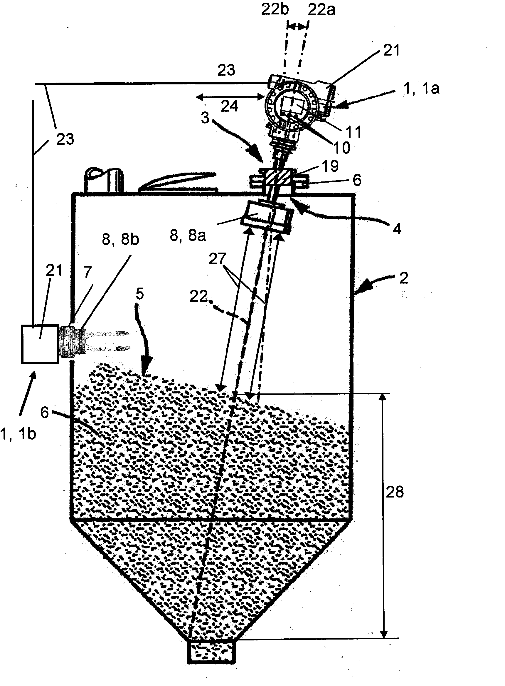
[0023] figure 1 Shown is a measuring device 1 a installed in a spout 4 on a container 2 , which uses the transit time measurement method to determine a level 21 of a medium 5 or filling substance 5 in the container 2 .

[0024] In most applications the measuring device 1 , 1 a is fastened via a flange 6 in the nozzle 4 on the container 2 . However, it is also possible to fix the measuring device 1 in the container 2 by screwing into the threaded opening 7 . figure 1 An option for mechanical orientation of the sensor unit 8 by means of a mechanical orientation device 3 is shown, such as a compression and a gas-tight ball joint. However, also other orientation devices 3 , such as, for example, rotating or swiveling wedges, flange assemblies, etc., can be used as the orientation device 3 .

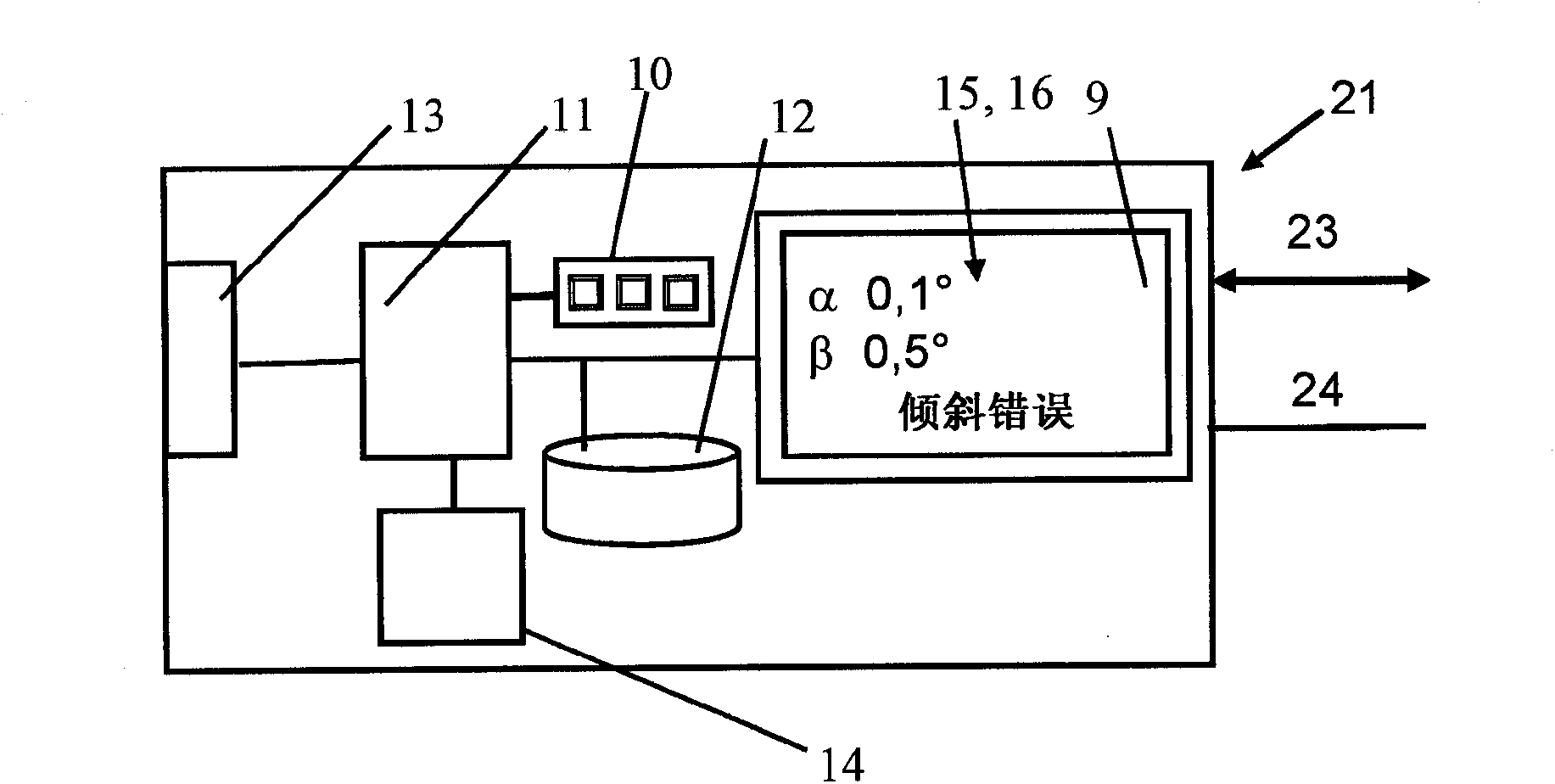
[0025] figure 1 A measuring device 1 is shown which essentially consists of a sensor unit 8 located in a container 2 and a measuring transmitter unit 21 located in a housing outside the ai...


PUM


Abstract

A measuring device featuring ascertaining and monitoring optimized orientation of the measuring device. Thus, the invention provides a measuring device for determining and / or monitoring limit level or fill level of a medium in a container, comprising at least one sensor unit and a measurement transmitter unit, wherein at least one inclination sensor is integrated in the measuring device for ascertaining orientation of the measuring device and / or the sensor unit on the container

Description

technical field [0001] The invention relates to a measuring device for determining and / or monitoring a limit or fill level of a medium in a container. The measuring device comprises at least one sensor unit and a measuring transmitter unit. Background technique [0002] Measuring devices manufactured and marketed by the assignee under the trademarks Micropilot and Prosonic, which operate according to the transit time measurement method and serve to determine and / or monitor the fill level of a medium in a container. In this travel time measurement method, for example, ultrasonic waves emitted by an acoustic transducer, or microwave or radar waves emitted by an antenna, and echoes reflected on the surface of a medium after a certain distance depending on the travel time of the signal is received back. From the travel time with the aid of the known propagation velocity, the level of the medium in the container can be calculated. In this case, the echo curve represents the am...

Claims


Application Information

Patent Timeline
Patent Type & Authority Applications(China)
IPC IPC(8): G01F23/284G01F23/296
CPCG01F23/284G01F23/00G01F23/2967G01F23/2962G01F25/0061G01F25/0084G01F25/20
Inventor 哈拉尔德·法贝尔斯特芬·马可尼佛朗哥·费拉多
Owner EHNDRESS KHAUZER GMBKH KO KG
Learn More