Swing arm continuous polishing machine

A technology of arm rings and racks, which is applied in the field of swing arm ring throwing machines, can solve the problems of limited size range, etc., and achieve the effects of increasing the processing range, improving market competitiveness, and improving resource utilization.

Active Publication Date: 2013-10-16
成都川威机械制造厂
View PDF4 Cites 12 Cited by
  • Summary
  • Abstract
  • Description
  • Claims
  • Application Information

AI Technical Summary

Problems solved by technology

The size range of products processed by this equipment is limited

Method used


Image

  • Swing arm continuous polishing machine
  • Swing arm continuous polishing machine
  • Swing arm continuous polishing machine

Examples


Embodiment Construction

[0018] The present invention will be described in further detail below in conjunction with specific embodiments and accompanying drawings.

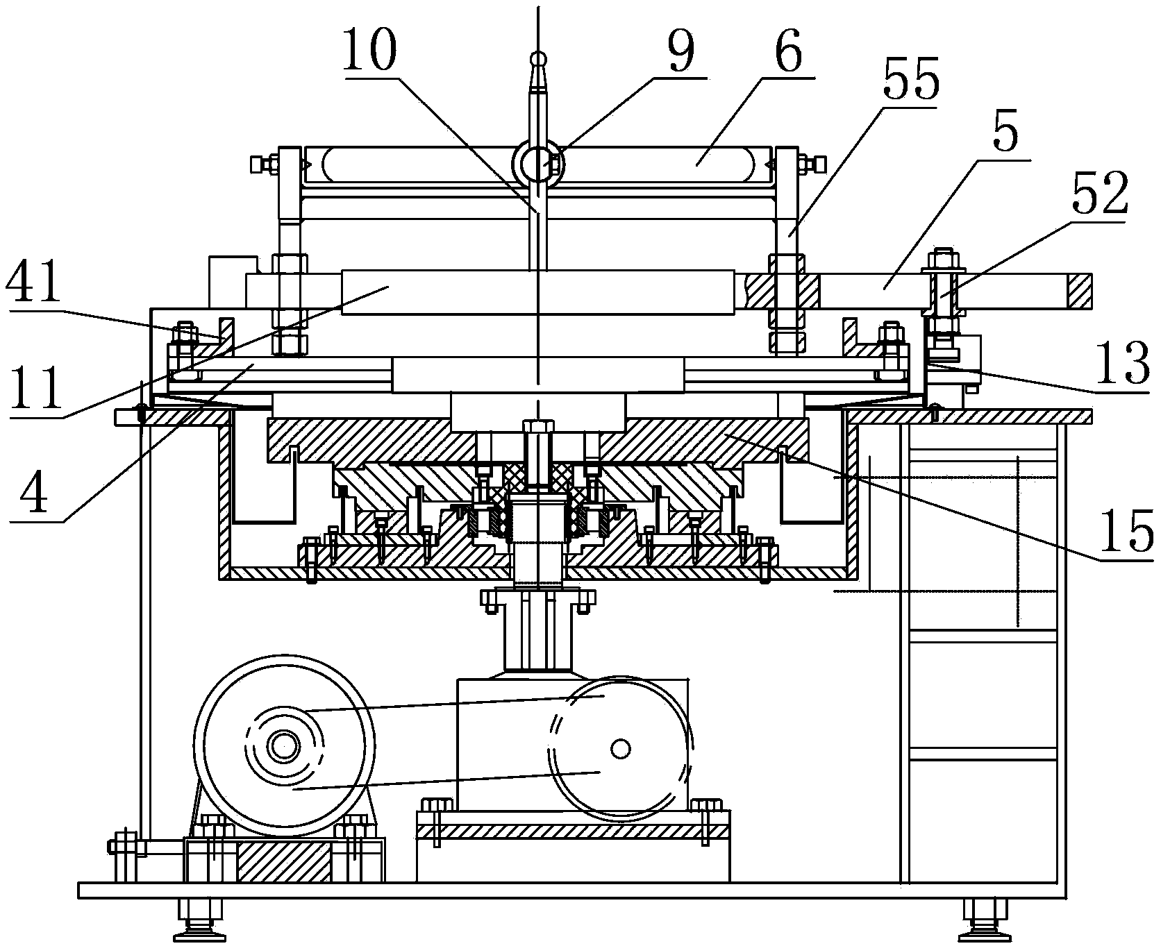
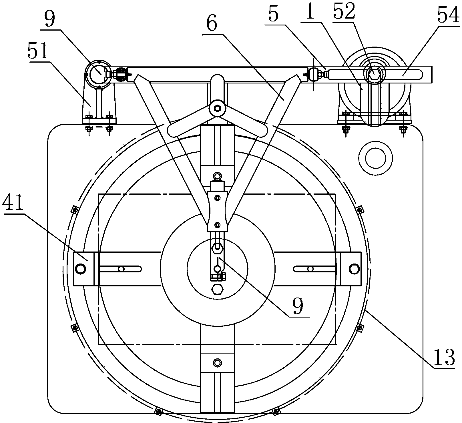
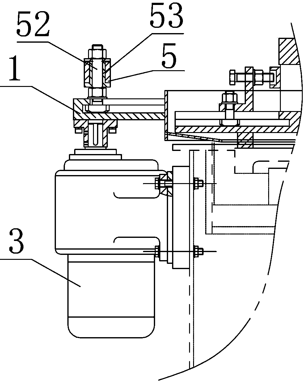
[0019] a kind of like Figure 1-3 The shown swing arm ring throwing machine includes a frame, a positioning chuck 4 that is horizontally arranged on the frame and used for positioning a workpiece, and a first grinding tool 11 that is arranged on the frame by a swing arm structure. The first grinding tool 11 is above the positioning chuck 4, wherein the swing arm structure includes a swing bar 5 with one end hinged on the frame, and the first grinding tool 11 is positioned on the swing bar 5 by a support arm , the other end of the swing rod 5 is driven to and fro by the rotation of an eccentric swing plate 1.

[0020] The present invention is a new design, and can also be improved on the basis of the existing ring throwing machine, mainly by adding a swing arm structure and a positioning chuck 4, so that the equipment can be restored to a...


PUM


Abstract

The invention discloses a swing arm continuous polishing machine which comprises a machine frame, a location chuck and a first grinding tool. The location chuck is horizontally arranged on the machine frame and used for locating a workpiece to be machined, the first grinding tool is arranged on the machine frame through a swing arm structure, and the first grinding tool is located above the location chuck. The swing arm structure comprises a swing rod, one end of the swing rod is arranged on the machine frame in a hinged mode, the first grinding tool is located on the swing rod through a supporting arm, and the other end of the swing rod is driven by the rotation of an eccentric swing disc to perform the reciprocating motion. The swing arm structure is designed based on the prior art, and when the machine frame is a machine frame of an existing continuous polishing machine, the swing arm structure is arranged on the existing continuous polishing machine to achieve the powerful functions of the swing arm continuous polishing machine. The cost of a manufacturer for buying new equipment can be greatly reduced, the effective utilization on original equipment can be achieved, and the resource utilization rate is improved. The swing arm continuous polishing machine uses a millstone of the continuous polishing machine to serve as a workpiece carrier, the machining scope of the continuous polishing machine is greatly expanded, the machining accuracy is improved, and the market competitiveness of the swing arm continuous polishing machine is improved.

Description

technical field [0001] The invention relates to a swing arm ring throwing machine. Background technique [0002] At present, in the optical and electronic industries, there are certain limitations in the fine grinding and polishing equipment used for processing optical glass, quartz glass, crystal, sapphire, and silicon wafer planes, that is, the size of the components must be selected for processing. Only the equipment can achieve the processing effect. For example, a 620 large-diameter grinding disc can only process 310 large-diameter workpieces at most, which limits the scope of application of the equipment. If you want to process other types of workpieces, you have to purchase new equipment, which increases the cost of the enterprise. Investment costs and resource utilization are relatively low. [0003] The working principle of the existing ring polishing machine is that three groups of roller brackets are respectively equipped with two rollers. When the main motor dri...

Claims


Application Information

Patent Timeline
Patent Type & Authority Applications(China)
IPC IPC(8): B24B29/00B24B41/00B24B41/06
Inventor 冯思溶
Owner 成都川威机械制造厂
Why Eureka
Try Eureka