Method and device for collecting and treating sludge in shallow lake

A sludge and lake technology, which is applied in the field of collecting and processing shallow lake sludge and equipment, can solve the problems of secondary pollution of the environment, floating mud cannot be sucked up, drifting to other places, etc., and achieve the effect of reducing treatment costs and reducing costs

Inactive Publication Date: 2013-10-16
JIANGSU JUHUI TECH
View PDF6 Cites 15 Cited by
  • Summary
  • Abstract
  • Description
  • Claims
  • Application Information

AI Technical Summary

Problems solved by technology

Therefore, it is not only difficult to improve the water quality of shallow lakes by using grab buckets to collect silt, but also the floating mud cannot be sucked up, and the treatment effect is not good
Sludge is collected by a twist-suction silt collection device with a spiral cutting head, which sucks the silt to the shore while stirring the silt at the bottom of the lake. Due to the unevenness of the lake bottom, it is inevitable during the process of stirring and sucking the silt at the bottom of the lake. The ground will disturb the bottom of the lake, and the floating mud on the upper layer of the silt will drift to other places. Therefore, it is also difficult to remove the floating mud at the bottom of the lake to the greatest extent with the latter method, and the treatment efficiency is not high.
On the other hand, since the above two methods all need to transport the collected silt to the silt yard on the shore for treatment by means of a silt ship or a pipeline, they cannot be processed on-site, and transportation tools or pipelines for transporting the silt are required. make the management cost higher
In addition, due to the need to set up a silt storage yard on the shore, it not only occupies cultivated land, but also causes secondary pollution to the environment

Method used


Image

  • Method and device for collecting and treating sludge in shallow lake
  • Method and device for collecting and treating sludge in shallow lake

Examples


Embodiment Construction

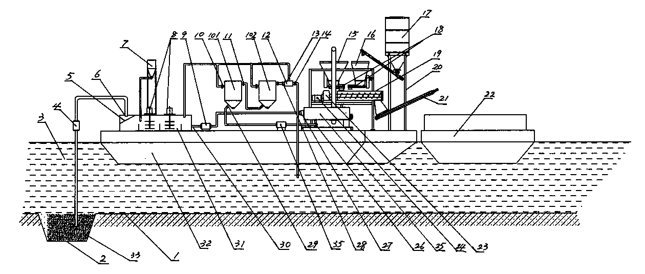
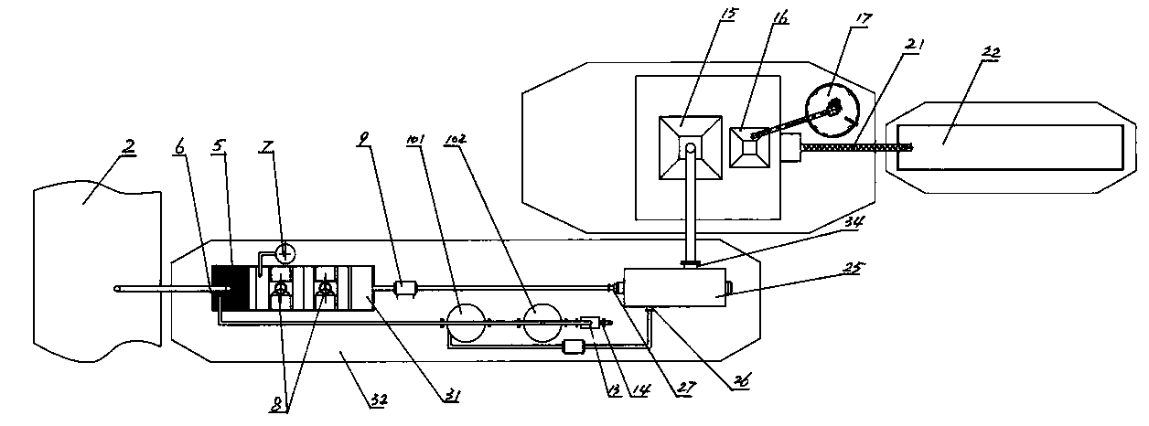
[0026] The method for collecting and processing shallow lake silt of the present invention is described in further detail below in conjunction with embodiment:

[0027] The method of collecting and processing shallow lake silt of the present invention comprises the following steps successively:

[0028] Excavate ridges 2 on the lake bottom 1 in advance, and the ridges 2 are arranged in a staggered shape, so that there is a relatively large angle (preferably 90 degrees) between the longitudinal direction of the ridges 2 and the perennial lake flow direction, so as to make the lake bottom float. Mud can enter the ditch 2 under the action of the lake current. Wherein, the number of the furrows is determined according to needs, and in this embodiment, there are five furrows in the same direction (ie, horizontal and vertical).

[0029] When the silt in the ditch 2 is full and needs to be removed, a floating platform 32 and a mud ship 22 are arranged on the lake near the ditch 2 . ...


PUM


Abstract

The invention discloses a method and a device for collecting and treating sludge in a shallow lake. The method comprises the following steps: digging a ditch at the bottom of the lake in advance, arranging a floating platform on the lake surface near the ditch, arranging a sludge treating device on the floating platform, pumping the sludge in the ditch into a mud sump, stirring the sludge in the mud sump, separating mud from water, solidifying and the like. The device comprises the mud sump, a mud and water separator and a sludge solidifying device, and is characterized by further comprising the floating platform, wherein the mud sump, the mud and water separator and the sludge solidifying device are arranged on the floating platform; relatively dry solidified sludge is transported to a place requiring the sludge by a sludge transporting ship. By the method and the device for collecting and treating the sludge in the shallow lake, not only can the water quality of the shallow lake be improved, the control effect can be improved and the control cost can be reduced, but also arable land is not occupied and secondary pollution to the environment is avoided; sludge at the bottom of the shallow lake can be collected on the water surface of the shallow lake and treated on site.

Description

technical field [0001] The invention relates to a sludge treatment method and device. Specifically, it is a method and a device for collecting and on-site treating the silt in the shallow lake on the water surface of the shallow lake. Background technique [0002] Everyone in the inland lake treatment industry knows that the silt in shallow lakes needs to be collected and treated regularly, otherwise, with the increase of silt, not only the water storage capacity of the lake will be reduced, but also the water quality of the lake will be reduced. At present, there are two main methods of sludge treatment in shallow lakes. One method is to use grab buckets to grab the sludge at the bottom of the lake onto the mud ship, and then transport the mud to the shore by the mud ship. The subsequent treatment such as stirring, mud-water separation and solidification treatment; another method is to first use a cutter-suction sludge collection device with a spiral cutting head to stir t...

Claims


Application Information

Patent Timeline
Patent Type & Authority Applications(China)
IPC IPC(8): C02F11/00C02F11/14C02F11/12
Inventor 满志清
Owner JIANGSU JUHUI TECH
Why Eureka
Try Eureka